[quote author="rob_gould"][quote author="uwi20040"]
I have 2 pictures but I don`t know how to upload them here...
[/quote]
[quote author="uwi20040"]
Does anybody help me out with the wiring of the VTB 9045 and VTB 9046 ? Are the two primary and two secondary sections in serial ?
Uwe[/quote]
I'd also be interested in this if anyone could post?[/quote]
From page 6
Hi!
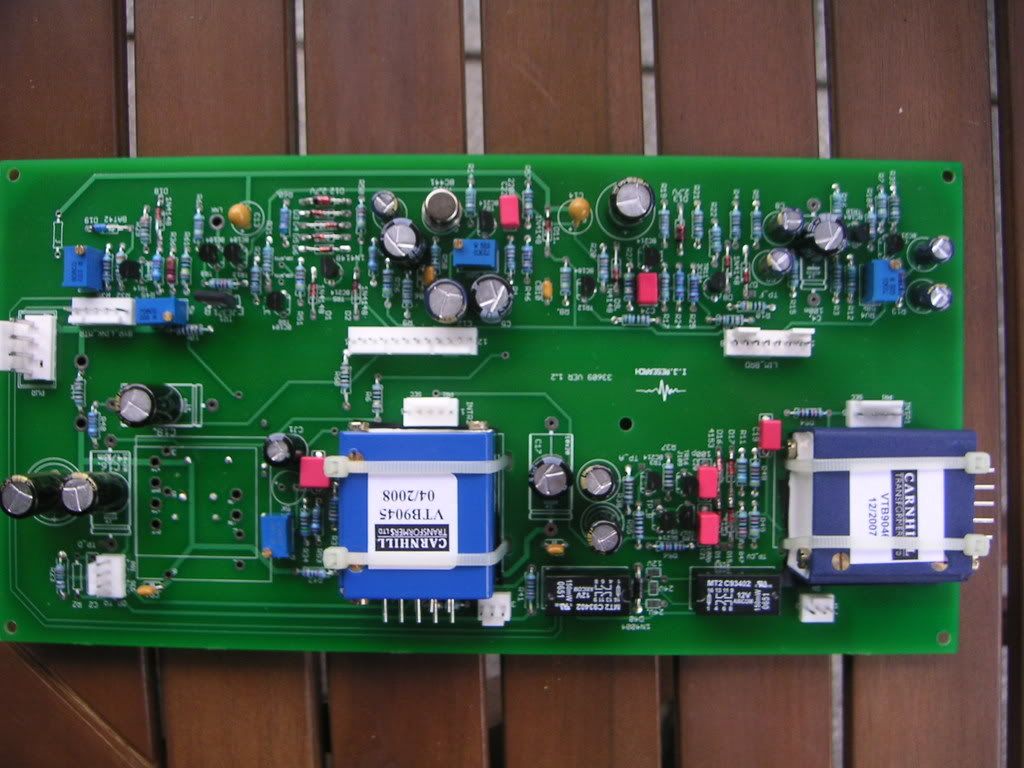
It is impossible to fit Marinairs direct to pcb.
Their height is 37mm, add pcb twice, it comes to 80 mm,
there's no enough height iside 2RU rack.
Use 5 pin Molex connectors for this purpose
marked INTR1 and INTR2.
Pads are marked pri, +, -, G, sec, +, -.
Just put small boards with holes beneath your Marinairs,
fix them with cable nylon ties (strips), and solder directly to 5-pin connectors with wires.
Pri's in series and sec's in series.
That's all!
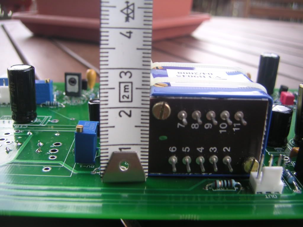
-------------------------------------
Pri +
Pri - 5
Connect 3 - 4
G = 6
Sec + 7
Sec - 10
Connect 8 - 9
Leave 11 NC
That's how i've done it.
But haven't powerd mine up yet, so hope this is the right way.