Official 33609 builder's tread. See 1st page for updates.

GroupDIY Audio Forum

Help Support GroupDIY Audio Forum:

This site may earn a commission from merchant affiliate links, including eBay, Amazon, and others.
Igor , do you get all the adress data from tat ??

..another thing , all the 470u Elko`s in the audiochain..anybody bypassed this thingis already or do they "contribute"to the N-sound too much ?

Big Greets ,
Ax
 
Hopefully all will get their pcb's on time ;)
470u Elco's? I like them. More distortion comes from trunnys anyway ;)
 
Updated BOM again. Fixed connectors and electro caps under Tant heading.

Need some info on the following caps still:

Values for:

Comp/Limit motherboard:

Values for CB1,4,6,10?
I assume these are bypass caps hence the "b"?

PSU board:

C2 just says .1


EDITED (1 more time) to remove some of the stupidity....

Thanks!

Josh
 
I was just noticing that C1 and C2 (right off of the interstage transformer's primary) on a revision A are 3V tantalum while on the J revisions (and in this project) are listed as electrolytics. Anyone have an idea how this would change the sound? I would think it would have sinnificant impact being right in the signal path... I suppose I could get both and try them- any reason not to?

It looks like the voltage coming off of TR3 and TR4 is 4v (on Igor's schem) so maybe 6V for C1 & C2 is appropriate?

Thanks,

J
 
JDJ

I'll have a little time this weekend to give some help on a BOM, shoot me a email from my email link and give me a direction to go.

Kevin
 
I used C1 and C2 470u 16V Elna's in one unit and Nichicon IIRC in other.
More color coming from trunny's, so, just use good quality caps there.
 
In Neve tradition these large caps on amp stage outputs are usually electrolytic, just as the input caps on amp stages are usually tantalum.
I am quite surprised that they used tantalum in this position on some units.


BTW, did you send the pcb's Igor?
 
What does the meter show? Is it traditional VU-style with the needle sitting at zero when idle and going negative to display compression?
- or -
does it go from left to right to display amount of compression?

Also, is it possible to change the background in the sifam to a custom design?
If so we should post design ideas!

/Marco
 
[quote author="Yellowguy"]
does it go from left to right to display amount of compression?[/quote]

Yes, quite sure it does ...look at a pic of the original with the Director 14

http://www.soundtools.co.uk/Images_T1/Products/Neve/Hi%20Rez/33609.bmp


[quote author="Yellowguy"]
Also, is it possible to change the background in the sifam to a custom design?
[/quote]

Yes..
 
Comp/Limit motherboard:
Values for CB1,4,6,10?
I assume these are bypass caps hence the "b"?
PSU board:
C2 just says .1
Values for CB1,4,6,10 are 0.047-0.33 uF 50v ceramic caps 5mm pitch
These are yes, bypass caps for power supply
PSU board C2 same as CBxx

Yes, BOM is for one channel.
 
FOR LUCKY ONES WHO RECEIVED PCB'S ALLREADY....

33609 COOKING RECEIPT

WATCH ADDAMS FAMILY 3-4 TIMES FOR GOOD STATE OF MIND,
OR PUT YOUR FAVORITE LP.


AT FIRST, CHECK ALL RESISTORS, TRANSISTORS, ETC FOR RIGHT VALUES/POLARITY.
CHECK ALL WIRES ACCORDING TO SCHEMATIC AND PICTURES.
IF USING TRAFOS IN METAL CANS, BE SURE NO SHORTS, THERE'S TWO BLANK
SMALL PCB'S WITH HOLES TO PUT THEM BENEATH THE TRUNNY'S ON MOTHERBOARD.
CHECK TWICE TRUNNY'S ARE NOT REVERSED, ETC.
BE SURE NO CONTANINATION ON PCB.
THEN, CONNECT POWER TRAFO TO POWER SUPPLY AND CHECK OUTPUT VOLTAGE IS 24V+/-3%.

33609 FIRST FIRE-UP

CONNECT POWER SUPPLY TO MOTHER PCB, CONNECT BYPASS PCB, METER, FRONT PANNEL PCB'S.
PUT 5K POTENTIOMETER ON BA340 TO CCW (LEFT) POSITION.
MEASURE VOLTAGE ON R44, 10R0, AND ADJUST TRIMPOT ON BA340 TO GET 250-280 MV READING,
LEAVE THE UNIT FOR 5 MIN AND RE-ADJ. IF NEEDED.
MOST OF PEOPLE THERE HAVE A MEASUREMENT SETUP OF SOUNDCARD, SCOPE AND MULTIMETER.

HERE'S ADAPTED MINIMIZED TEST PROC.

NUMBERE ARE ACCORDING TO ORIG.TEST PROC.
3.2.ADJUST YOUR SOUNDCARD FOR 0.775 V AC OUTPUT, IT IS 0DBU @600 OHM
GO TO 3.3, 3.4, 3.5, 3.6

SECTION 4.
4.0. ON POWER SUPPLY BOARD, ADJUST R6 (POT NEAR OP-AMP) FOR 3,00V ON +CV PAD TO GND (-CV PAD)
YOU HAVE 3.00 V SOURCE FOR CALIBRATING DIODE BRIDGE VCA.
4.1. APPLY 0DB TO INPUT. COM OFF, LIM OFF, BYPASS IN, MEASURE OUTPUT IS 0 DB,
CONNECT LINK TO CV 3.00V WITH CROCODILE CABLE. ADJUST RV2 TO GET -8 DB AT OUTPUT.
LET UNIT HEAT-UP 5 MIN, REPEAT.
4.2. APPLY 0DB TO INPUT. COM OFF, LIM OFF, BYPASS IN, MEASURE OUTPUT IS 0 DB,
CONNECT LINK TO CV WITH CROCODILE CABLE. ON POWER SUPPLY BOARD, ADJUST R6
(POT NEAR OP-AMP) FOR -20DB AT OUTPUT.
ADJUST METER POR RV3 FOR -20 DB READING ON METER.
GOTO 4.0, WATCH -8 DB ON METER AT 4.1, MEASURE -8 DB OUTPUT, RE-ADJUST IF NEEDED,
REPEAT IF NEEDED, GOTO 4.2, EXIT LOOP.
VCA DEPENDS ON ROOM TEMPERATURE, AND ADJUST BOTH BOARDS AGAIN WHEN UNIT IS FINNISHED
TO GET PRECISION COMPRESSOR.

4.3. APPLY MAX. OUTPUT FROM SOUNDCARD TO INPUT, AT LEAST +10DBU,
LIM IN, ATT FAST, RECOVERY 50, LIM THRESHOLD TO +4, COMP OFF,
ADJUST RV4 TO +4 AT OUTPUT.

FOR 4.4-4.7, CHANGE LIM RECOVERY, PUT LIM IN-OUT, SEE RECOVERY ON SCOPE.
IF UNIT DONE WITHOUT ERRORS, ALL SHOULD BE FINE.

GOTO 5.1.

5.2, LIM OFF, INPUT 0DBU, COM THRESHOLD 0DB, MAKEUP 0, RECOVERY 100, RATIO 6, COM SW OFF.
MEASURE OUT IS 0DB.

PUT COM SW IN, MEASURE OUT IS 0DB, PUT COM THRESHOLD TO -2, MEASURE OUT IS -1DB,
ADJUST RV5 IF NOT.

INPUT ODB, THRESHOLD -20DB, MAKEUP 0, RECOVERY 100, RATIO 6, COM SW OFF.
MEASURE OUT IS 0DB.

PUT COM SW IN, MEASURE OUT IS AROUND -16DB.
ADJUST RV5 IF NOT.

GOTO 5.2 AND CHECK 0DB THRESHOLD AGAIN, ADJUST BOTH L AND R CHANNELS FOR SAME COMPRESSION.

CHECK RECOVERY SAME AS IN LIMITER SECTION.

GOOD LUCK!
 
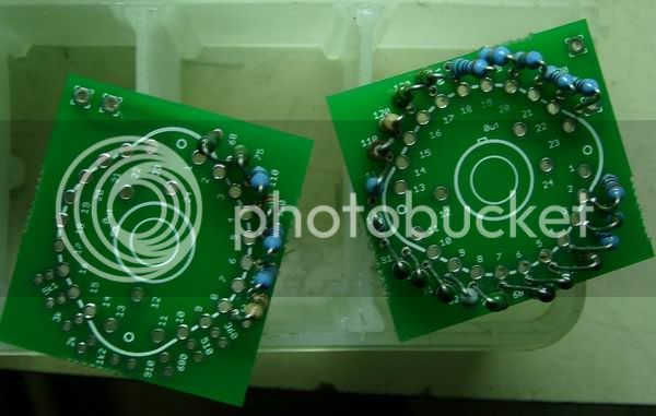
Just started to stuff the switch pcbs and need to check I haven't made a noobish error already. I'm certain this isn't a problem but want to confirm...

The way I've soldered the resistors to the circuit board is from inside to out

picture.jpg


the opposite of Igor's version here which is from outside to in.

elma_1.jpg


This isn't a problem is it?

Please excuse the basic question. I'm still learning :?

Cheers,

Rob
 
[quote author="guavatone"]The BOM is for 1 channel, right? -at least for the switch PCBs I think?[/quote]

Correct- both my and the initial Igor BOM is for one channel. Thanks to Kazper, I'll be updating shortly.

-Josh
 
dont worry rob, shouldnt be a prob, its just easier to see everything the other way. relax and have a brew :grin: :thumb:

:guinness:
 
JDJ,
Once my boards arrive to me in the states, I'll help out on caps with spacing issues on the BOM. I'll send you a Email or PM when I got my boards.
 
Looks like I needed to revisit the first page, sorry to post something so silly. What I'm after is other than looking for NOS or cannibalized parts is Carnhill making any of these parts and are they reasonably available?
 
[quote author="lofi"]dont worry rob, shouldnt be a prob, its just easier to see everything the other way. relax and have a brew :grin: :thumb:

:guinness:[/quote]

Erm oh yeah I see what you mean now. Beginners eh! :roll:

Cheers Ian :thumb:
 
[quote author="JdJ"]... what does:
CPOL-EUE3.5-8
refer to in:
2 100ux50v CPOL-EUE3.5-8 C5, C7
[/quote]

My guess is Capacitor - Polarised - EUE I'm not sure - pitch between 3.5 and 8mm.

Maybe :?:
 

Latest posts

Back
Top