


Also:
Now that it is more or less working...
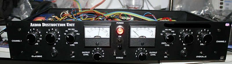
Anders meters, Carnhill iron, MEC switches, Piher pots, Banzai aluminum knobs. I went for a batman black-black-black scheme . Just have to dial in the level of distortion I'm getting and figure out the overdrive switch, but other than that it's working and sounding nice big and fat! Samples when I get it under control..
Now that it is more or less working...
Anders meters, Carnhill iron, MEC switches, Piher pots, Banzai aluminum knobs. I went for a batman black-black-black scheme
. Just have to dial in the level of distortion I'm getting and figure out the overdrive switch, but other than that it's working and sounding nice big and fat! Samples when I get it under control..


