The Rude Tube Build / Support Thread (MAJ + PSU)

GroupDIY Audio Forum

Help Support GroupDIY Audio Forum:

This site may earn a commission from merchant affiliate links, including eBay, Amazon, and others.
jandoste said:
Hey Bernd,
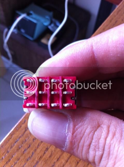
I can't understand Jerome's connexion...

"Connect 4 on right middle pin and up pin right (Up pin right sort with middle pin left) Connect 1 on up pin left.
Connect 2 on down pin left
Connect 3 on down pin right"

Can you  make a basic shcema for this switch connexion please?


Thanks

I was also confused by this description until I looked at the datasheet for a SP3T switch. It is easier to understand if you just look at the schematic and make your connections for the switch on the datasheet. Look here on 5th page: http://www.mouser.com/ds/2/295/MtogglesBushing-31423.pdf

Hope this helps,

Brian
 

Attachments

  • SP3T switch.jpg
    SP3T switch.jpg
    23.5 KB · Views: 64
Hi,
I had to scratch my head for a few hours as well. I finally came to this solution. Drawing attached. solder together the two pin in the middle (A). Give yourself 10 minutes and you´ll understand how to wire it.
regards
Bernd
 

Attachments

  • RT 3 pos schalter dpttononon.GIF
    RT 3 pos schalter dpttononon.GIF
    11.7 KB · Views: 123
Hi,
Take a look here. Jandoste's picture with the legend present in the PCB.
Solder the two pin with dash on the picture.
regards
 

Attachments

  • 911740_10200626793405974_1606840605_n.jpg
    911740_10200626793405974_1606840605_n.jpg
    53.8 KB · Views: 61
hi guys in few days i'm gonna build the rude tube and i want to know if someone have designed a stero link for this beautifull machine, and also if there are error before i start building.
thank you
 
I just want to tell any potential builders of the "Rude Tube" that I wont supply any  support for the pcb made by our member DRASK, since he designed the pcbs with my intensive support  and  later sold the pcbs without sending me as the designer of this project even a single set of pcbs. Send all questions related to this project directly to him. I don't feel responsible for any error or mistake related to his pcb.
Kind regards
Bernd
 
Hi benrnbrue 

i'm  just finishing my rude tube v1 with drask pcb but i dont understand  some wirings.
i have read all the topic about rude tube in this forum and don't find the answer maybe you can help me genius

-SQUISH &PAD (2 pins each on mainbord pcb)  i think it's a spdt switch but i'm not sure
-DI  i think it's a an unbalanced jack input but i'm not sure

i see your new project looks very good i think i will buid ivory after this one.

best regard
 
Squish jumper for standard use or, you could use a 1conductor shielded cable to 500k pot for variable compression or set up a spdt switch with fixed resistor. Pad you need to set up spdt switch. Pad 1 or left hole on pcb goes to common on the spdt switch pad 2 or right hole on pcb goes to bottom throw of single pole switch for the front panel. Top throw of switch would be left alone. Di is unbalanced, but there's 3 pads which is confusing. Looking at pcb left to right = pads 1,2,3. Pad 1 is ground. Pad 2 is the input transformer secondary output that shorts with pad 3  when no 1/4" jack is plugged into di. Pad 3 is output to ef86 tube. Pad 3 is tip, and pad 1 ground shield. Pad 2 is sleeve. Look at picture and see how the jacks tip and sleeve contacts short when no jack is inserted.
 

Attachments

  • W-SC-12A-T.GIF
    W-SC-12A-T.GIF
    60.3 KB · Views: 9
I'm building it with a couple of Jensen 11P1 in input and a couple of Jensen 123 ALCF on output (reversed).
Do i have to change the damping network on the out of the input transformer? Jensen recommend R=13k and C=620pF.
Do i have to omit the 100k resistor in parallel on output of the input transformer also?
 
13k and 620pf will make up your zobel network. http://www.jensen-transformers.com/datashts/11p1.pdf The schematic says to omit zobel network if you just use the 10k or higher shunt resistor. You could always run a square wave through the unit once done an observe on an oscilloscope if there is noticeable ringing in the output. Then you can tinker with the zobel network to isolate or damping the ringing.
 
Bobby Baird said:
13k and 620pf will make up your zobel network. http://www.jensen-transformers.com/datashts/11p1.pdf The schematic says to omit zobel network if you just use the 10k or higher shunt resistor. You could always run a square wave through the unit once done an observe on an oscilloscope if there is noticeable ringing in the output. Then you can tinker with the zobel network to isolate or damping the ringing.

Great. But i have to use the 100k resistor? or not?
The schematic says to omit the zobel network ONLY if the RL is 10k. In this case is 1M. And I've assumed I need it. Correct if I'm wrong.
 
Are you referring to this R1 100k resistor on the rude tube schematic? If so I never read any where in this tread to ever omit R1 because of a line level transformer. "R2 & C1" are to be omitted if using line level transformers. You might want to ask some transformer guru about your particular jensen. I read that the only time you need zobel is with a mic input transformer like 1:7 ratio. In that case you would need "R2 & C1." I would omit them first and test as I mentioned before then you would know if you need the zobel are not either way it will still pass audio and won't damage your transformer. Good Luck.
 

Attachments

  • Zobel.jpeg
    Zobel.jpeg
    24.1 KB · Views: 34
Here is my dream build. I call it "The Rude Tube Redd 47 Stereo Harmonic Distortion & Mic Pre. " Wu-who  that's long winded.
Here's the features: Sowter 9970 mic input tx 1:7 ratio. Sowter 9980 7:1 output ratio. 3 position drive switch. Mic line switch. Phantom power. Defeatable 6as6 Tube section for clean or dirty. Output Pad. Front panel Di. 500k Squish pot. Hpf & LPF. Polarity switch, and true bypass. Dang.
 

Attachments

  • The Rude Tube Redd 47.jpeg
    The Rude Tube Redd 47.jpeg
    21.2 KB · Views: 67
mrkrawn said:
-DI  i think it's a an unbalanced jack input but i'm not sure

best regard

The Di is unbalanced but you have to make sure the jack you bought is a shorting jack.  The 2 contacts on the jack should touch each other when no 1/4" plug is installed. 
 
I'm curious if any one here knows how to calculate the formulas for the LPF  and the Peaking filters caps? Say I want a 6khz or 10khz LPF, or a formula to calculate a 800 hz peaking filter. How would I come up with the value instead of just throwing in some arbitrary values? I know about this http://sim.okawa-denshi.jp/en/CRhikeisan.htm but looking at the schematic it doesn't jump out at me how to calculate. Say for the peaking filters what role does the inductor play in coming up with a value, and on the LPF all I see is a shunted cap no resistor involved.
 
Hi
I've got my rude tube working today .
it sound perfect in bypass mode but when i remove bypass i have a a strange hi pass filtered sound maybe the input or outpud transfo wire i will check.

i follow that but i'm sure there is an error :

Primaire WSM10K/10K (Input transfo)
Transfo Pin 1 => MB 1 (Input transfo / IN)
Transfo Pin 4 => MB 2 (Input transfo / IN)

Secondaire  WSM10K/10K (Input transfo)
Transfo Pin 5 => MB 1 (Input transfo / OUT)
Transfo Pin 6 => MB 2 DON'T CONNECT
Transfo Pin 8 => Mb 3 (Input transfo / OUT)


Primaire XS1100 (Output transfo)
Transfo Pin 2 => MB 1 (Output transfo / IN)
Transfo Pin 1 => MB 2 (Output transfo / IN)

Secondaire XS1100 (Output transfo)
Transfo Pin 7 => MB 1 (Output transfo / OUT)
Transfo Pin 8 => MB 2 (Output transfo / OUT)
 
Hi,
check the output transformer wiring according to the picture attached.  Note, the picture shows the bottom view.
Bernd
 

Attachments

  • XS1100 bottom view.JPG
    XS1100 bottom view.JPG
    8.4 KB · Views: 34

Latest posts

Back
Top