2254C build/support thread

GroupDIY Audio Forum

Help Support GroupDIY Audio Forum:

This site may earn a commission from merchant affiliate links, including eBay, Amazon, and others.
I'm having some really bizarre issue with my comps.  The short story is they work and sound fantastic, really really over the top fantastic.  Now for the long story...

-My ratio switch is a 12 pos switch, all the front panels I've seen have 5 pos marked, the first 5 positions (from ccw to cw) effect the sound then the remaining positions have no effect.  On the schem its a 12 pos switch with only the first 5 pos connected to anything.

-Similar issue with threshold, fully ccw behaves as expected and as the switch is turned behavior is normal, but after the fifth position the unit stops compressing.  By using the +10 switch, even with the limited range of the controls, I can get the full range of compression from a few dbs to heavy squishing with a 0dbu (0.777v) signal. 

-meters, they don't track exactly the same, in a non uniform way.  What I mean is, adjusting the threshold the needles will go from pretty close, to kind of off, then back then the other way.  It's always generally ok, but just kind of weird.  Also, the scale is very inaccurate, at both of the far ranges (20 & 2) it's pretty right on but in the middle it's off by quite a bit.

-release, on one channel the ccw position causes the compressor to "stick".  It's like it doesn't release at all.  Also, the wacky-ness of the meters really changes with different release times. 

In a way I'm not super concerned since it works, and sounds great but I'd like to see if I can get to the bottom of some of this mumbo jumbo.  I screwed up and didn't match the diodes, but the two channels are very closely calibrated.  On some settings as little as 2/10th of a db difference and sometimes as much as 7/10ths.

let me know what you think.
 
substitute said:
I'm having some really bizarre issue with my comps.  The short story is they work and sound fantastic, really really over the top fantastic.  Now for the long story...

-My ratio switch is a 12 pos switch, all the front panels I've seen have 5 pos marked, the first 5 positions (from ccw to cw) effect the sound then the remaining positions have no effect.  On the schem its a 12 pos switch with only the first 5 pos connected to anything.

-Similar issue with threshold, fully ccw behaves as expected and as the switch is turned behavior is normal, but after the fifth position the unit stops compressing.  By using the +10 switch, even with the limited range of the controls, I can get the full range of compression from a few dbs to heavy squishing with a 0dbu (0.777v) signal.  

-meters, they don't track exactly the same, in a non uniform way.  What I mean is, adjusting the threshold the needles will go from pretty close, to kind of off, then back then the other way.  It's always generally ok, but just kind of weird.  Also, the scale is very inaccurate, at both of the far ranges (20 & 2) it's pretty right on but in the middle it's off by quite a bit.

-release, on one channel the ccw position causes the compressor to "stick".  It's like it doesn't release at all.  Also, the wacky-ness of the meters really changes with different release times.  

In a way I'm not super concerned since it works, and sounds great but I'd like to see if I can get to the bottom of some of this mumbo jumbo.  I screwed up and didn't match the diodes, but the two channels are very closely calibrated.  On some settings as little as 2/10th of a db difference and sometimes as much as 7/10ths.

let me know what you think.

you need to set your lorlin to 5 stop...  its under the big nut... metal ring... take it off, and place it on position
you need to use...
better off match your diodes....
check your resistor values etc on controller board....
my VU's didnt act the same... but it compresses the exact amount...  i re_adjusted one VU, just for visual...
i hardly look at the VUs anyway...
 
hey guys,

another couple here, one finished, one a few knobs yet to get, i love these compressors....all sounding fab!

2254csif.jpg

2254both.jpg

2254csifl.jpg

2254in.jpg


cheers!

 
I noticed you skipped the molex connectors, they were really really time consuming to wire up, do feel like hard wiring the control boards had any disadvantages? Also, if you don't mind me asking, how are your meters tracking?
 
substitute said:
I noticed you skipped the molex connectors, they were really really time consuming to wire up, do feel like hard wiring the control boards had any disadvantages?

desoldering in case of service...  ;D
and sorry for answering your question, pete!
do you still have any meters left?
cheers, alex
 
Yes Matta has the best answer, providing you dont have any problems then great, next time ill do just one side. Luckily I had no problems!

No meters left im afraid Alex,

my meters Track 100% correctly. do you have issues with that then?

Pete
 
my meters Track 100% correctly. do you have issues with that then?
Yeah, I think I might pull out all my diodes and re do it with matching parts.  When matching diodes are we just trying to get say, D1 on channel one to match D1 on channel two or are there pairs with each channel that should be matched?

How are other folks meters matching the scale?  Meaning, if I monitor my gain reduction in PT or with a dmm, at 20dbs and 2dbs things are pretty accurate but in the middle range my meters might show 12dbs where I'm actually getting 8dbs of reduction.

Right now the unit is at a friends studio and we here in philadelphia are experiencing what the local news has called "snowmageddon" so unfortunately I can't investigate the issues with the controls right now.

 
Have you calibrated the unit? You really have to calibrate it to make any kind of assessment, the last 2U stereo unit I did I got 0.124 and 0.120 where the ideal is 0.123 at the end of the calibration, that is about .1dB difference between the units, I matched the diodes as best I could.

Follow the calibration procedure a few pages back... if I get some time I might flesh it out a bit more from what Kambo has shared with the dBu in references to Volts AC RMS.

Cheers

Matt
 
i know... nuts!!  ??? 8) sinestaraudio - these look BETTER than the real thing.

how did you do those panels? powder coat then engrave? or is it silk screened? what typeface did you use?

and those vertical sifams look awesome too...
 
Hi Chaps,

ha ha, im not sure if throughing up in your mouth is a good thing or not! ha!  ;D

Still, with these I used a standard grey spray paint, and then engraved them on my CNC, I just used a standard arial font if i remember right.

Still have a few things to work out on the panel paint / paint fill-in as i still get a few problems i need to work out, but im getting there..

Cheers!
Pete

 
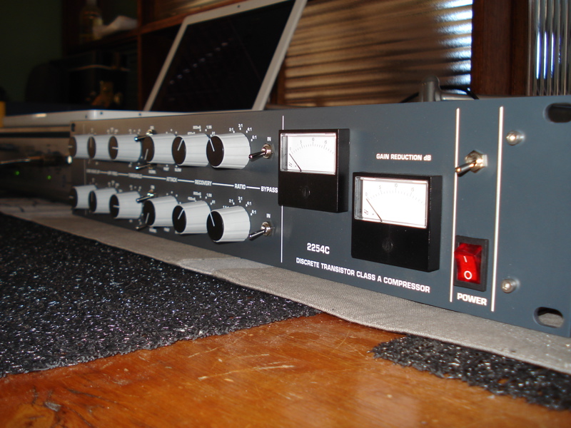
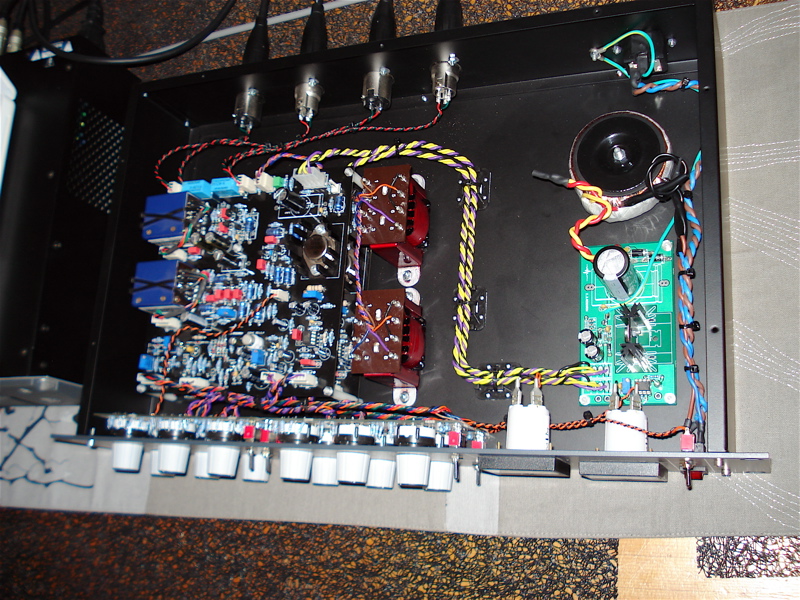
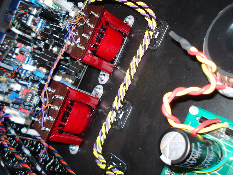
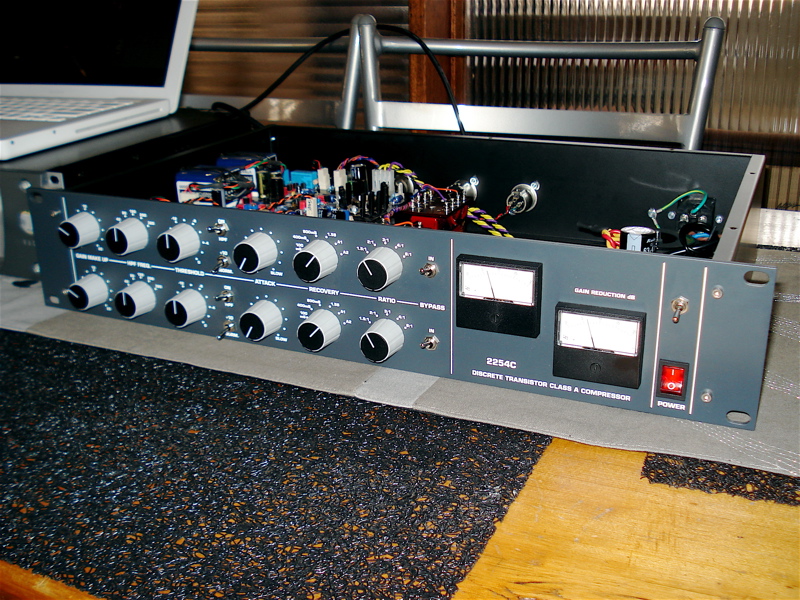
Thought I'd add to the inspiration... here are some pics of a 2U stereo unit I just calibrated... forgive the lovely placements and runner... busy building my new workshop so working off the dining room table at the moment, LOL!!!

2254c_front.jpg


2254c_front_angle.jpg


2254c_guts.jpg


2254c_guts_close.jpg


Cheers

Matt

 
Right, as promised here is a point by point calibration procedure based on the bits I got from Kambo, Igor and various other sources (thanks to you all for your insight/info along the way).

Before we start we need to set the BIAS current on the output stage of the BA283, the easiest way to do this is to adjust RV1 to give you a 100mA across R"7, the 47R resistor. Logic/Ohms law dictates that 4.7VDC across the 47R resistor is 100mA, so adjust RV1 to give you 4.7VDC across it... simple and effective, no scope required!

Moving on...

Make sure the settings on the control board are as follows:

MAKE-UP GAIN = 0
THRESHOLD = Fully Clockwise
ATTACK = 8 o'clock
RELEASE = Fully Counter Clockwise
RATIO =  1:2
+10 and HPF switched OUT
Compression IN

We then need to set the +CV voltage, which is done on Igor's PSU so adjust the onboard trimmer on the PSU to give you +3VDC at the +CV out.

With the compressor switched in adjust GAIN trimmer to get unity gain.
Then croc clip the +3VDC C+V voltage from PSU to the LINK on Main Board
Adjust RV2 to get -8db (0.308VAC RMS) at output XLR
Adjust the +CV trimmer on PSU for -20db / (0.0775VAC RMS) at output XLR
Adjust RV3 to reflect 0db on Meter
REMOVE the croc clip to the main board and PSU
Set the Threshold to -2db (1st click on the Threshold switch)
Adjust RV5 for -1db / 0.690 at output
Set the Ratio to 6:1
Set the Threshold to -20db and measure -16db / (0.123VAC RMS)
Adjust RV3 to reflect this accordingly

If all goes well your unit should be fully calibrated!

Happy compressing  ;D

Cheers

Matt
 
sinestaraudio said:
Hi Chaps,

ha ha, im not sure if throughing up in your mouth is a good thing or not! ha!  ;D

Still, with these I used a standard grey spray paint, and then engraved them on my CNC, I just used a standard arial font if i remember right.

Still have a few things to work out on the panel paint / paint fill-in as i still get a few problems i need to work out, but im getting there..

Cheers!
Pete

Hey Pete,
It was good throw up.

Cheers!
 
Hey Matta, I have calibrated mine and they are working well for the most part but there's a few issues that I need to clear up.  Mine are about 0.2 off from each other at the end of the test procedure.  But, if I feed a 0db signal, and monitor my gain reduction externally, going through each step of the threshold and ratio they drift by as much as 0.7 at some settings.  Also, while my meters are set accurately in use they aren't really behaving right.  What I mean is that through out the test procedure my measurements are pretty right on.  However if I test the actual drop in voltage and convert it to dbs at settings some where in the middle like threshold at -12 and ratio at 3:1, while the gain reduction is pretty close on both channels and the meters are in about the same position they indicate that the gain reduction is "x" when it's actually "y".  I was wondering if anyone else had experienced this.  I assume if I go back and match my diodes they might stand up a little straighter. 

looking at your procedure I noticed this, as a point of confusion.  I guess it's just a question of what scale you are using (I'm using Igors) but to be clear, when setting the PSU for -20db we are adjusting the meter to be to the far right of whatever scale is being used.  Is that correct?

Adjust the +CV trimmer on PSU for -20db / (0.0775VAC RMS) at output XLR
Adjust RV3 to reflect 0db on Meter

- Adjust Pot on PSU for -20db at output
- Adjust RV3 for 20db on meter

 
as long as you are reading correct measurements with your DMM you are fine...
VU is just a cosmetic... dont forget you have 2 resistors connected to your VUs, if they are
off tolerance you will get different reaction for sure... you should be able to get correct reading by adjusting
VU adjustment trimmer...
you need to match your "4x2=8" diodes for good stereo image...

far right is 20db or whatever point on VU you want... feel free to do your own scale...
once you mark your 20db, then you markup your 8db and so on....
i use one with 10db scale on mix_buss, one with 20+db(0db on VU) on drum buss :)
 

Latest posts

Back
Top