[BUILD] NU VARIMU 436 build & help thread

GroupDIY Audio Forum

Help Support GroupDIY Audio Forum:

This site may earn a commission from merchant affiliate links, including eBay, Amazon, and others.
Very interested in this project.. not too many people here seem to have done this vari-mu.
Is it possible to get some sound demos?
 
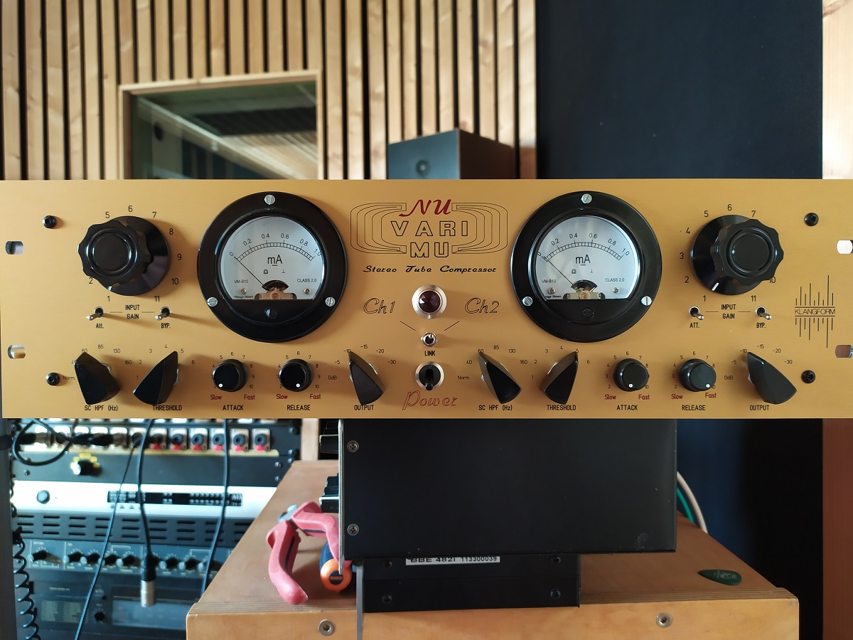
Here is my version:
sndx1.jpg

 
Hey  All,  ;)

Can someone briefly explain the function of each three tubes in this design please ?
I’m in the process to build one but I like when I understand what I do  ;D

Thank you in advance guys!!
 
Ayman59 said:
Hey  All,  ;)

Can soleone briefly explain the function of each three tubes in this design please ?
I’m in the process to build one but I like when I understand what I do  ;D

Thank you in advance guys!!
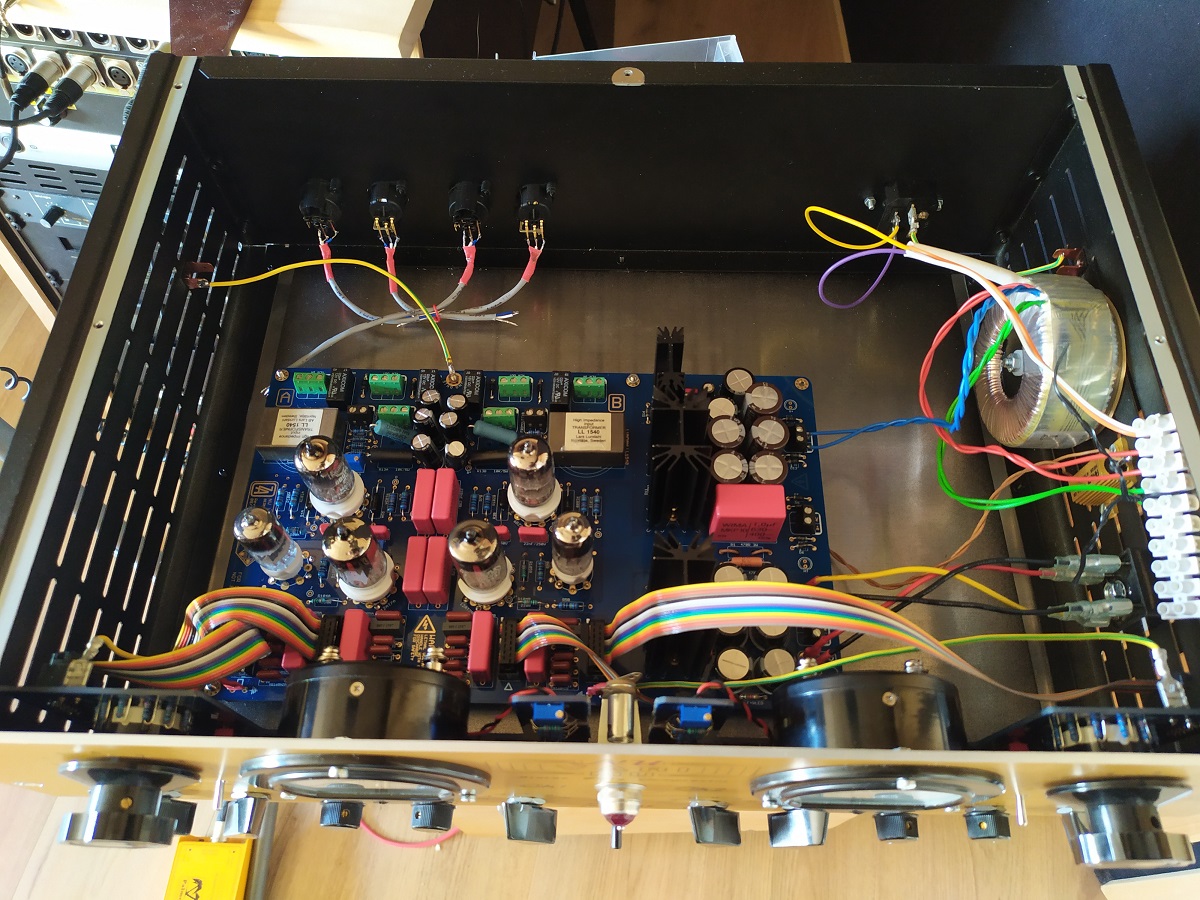
The 6BC8 is a vari mu valve & actually performs the gain reduction.  The 6CG7 is an amplifier valve that boosts the signal for the output tranformer & provides a strong signal to drive the side chain.  The 6AL5 is a double diode that rectifies the sidechain signal & makes into one that only goes negative.  The side chain signal needs to be negative going because by making the voltage between the grids & cathodes larger on the 6bc8 turns the gain down.
 
electrisizer said:
Im raedy for the Sowters OP TX, but they will arrive at the earliest in august :( what a production time...
as suggested i dont fire it up till then.

tubes are NOS mullard 6bq7a, siemens ecc81 and GE electron eaa91

mnn6t5f6.jpg


tiadxozm.jpg

Woaaaaaaw such a beauty  :eek: Good job electrisizer  ;)
 
Hi folks,

Maybe a dummy question but... for the 8650 OP tx is the mumetal can option mandatory or the fully shrouded style S will make the job as well? I mean if they are mounted onthe side on the opposite side of the power trafo, is there any noisy risk?

Thx for your lights ;-)

Jérôme
 
Ayman59 said:
Hi folks,

Maybe a dummy question but... for the 8650 OP tx is the mumetal can option mandatory or the fully shrouded style S will make the job as well? I mean if they are mounted onthe side on the opposite side of the power trafo, is there any noisy risk?

Thx for your lights ;-)

Jérôme

I used the open frame version on both of my builds with no issues.  I also had it working with an open frame Edcor with no issues. It sounds good with both the Edcor or the Sowter.
 
Holger said:
What Edcor have you used here?

I think it was an xsm 10k:600, although I'm away from home at the mement so not too sure.  People have said it isn't specced for the d.c but it worked fine while I was testing it,  I then swapped them for the Sowter.    I have experimented with a gain cell using  4x 6bc8 in parallel with that edcor too & that worked well & sounded nice.
 
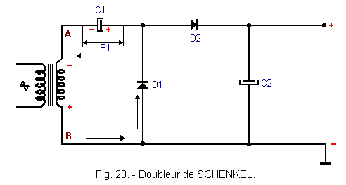
hello i use the don audio power trafo with 5V AC for V+ (measured 6v).

i tried the voltage doubler mod, as my relays are 12v:

Doubleur_de_SCHENKEL.GIF


but this mod and all mods ive found will generate a multiplied "DC" voltage.

in my case voltage is rised to +15V/0V (GND)DC . but this dosent seem to work... dont i need 12v AC?
by engaging the bypass switch relays dont "click"

(i havent connected the XLR or Out TX if this is important for the relay circuit)
 
Rob Flinn said:
I think it was an xsm 10k:600, although I'm away from home at the mement so not too sure.  People have said it isn't specced for the d.c but it worked fine while I was testing it,  I then swapped them for the Sowter.    I have experimented with a gain cell using  4x 6bc8 in parallel with that edcor too & that worked well & sounded nice.
Danke
 
by engaging the bypass switch relays dont "click"

EDIT: this is just a reminder, nothing to do with th relay ctrl, i just bumped that here again, someone asked me....don' forget to check that the Frontpanel PCB' are connected to Gnd, there are pads for that, to use Faston or hardwire.

Also check if the hardwired mods are still present under the board, and that the Relay Diodes pre-installed have some pins connected to gnd on Top Copper.
Just to take out that part, as i double check on sending but again who knows... shipping /handling could have fragilise the solder links of the hardwiring or whatever...
Anyway, check to take that part out of the way, if the Supplied voltage is accroding to your Relays min/max Voltages and if the Ribbon wiring etc... is all good, then there should not be any problems on relay clicking.


Best,


T.
 

Latest posts

Back
Top