KA-Electronics.com Mastering Tools, Kits, Vintage Semiconductors, Power Supplies and More

GroupDIY Audio Forum

Help Support GroupDIY Audio Forum:

This site may earn a commission from merchant affiliate links, including eBay, Amazon, and others.

user 133392

Well-known member
Joined
Dec 13, 2022
Messages
300
KA-Electronics.com Mastering Tools, Kits, Vintage Semiconductors, Power Supplies and More

https://ka-electronics.com/shop/
https://ka-electronics.com/shop/index.php?route=product/category&path=60https://ka-electronics.com/shop/index.php?route=product/category&path=66https://ka-electronics.com/shop/index.php?route=product/category&path=67
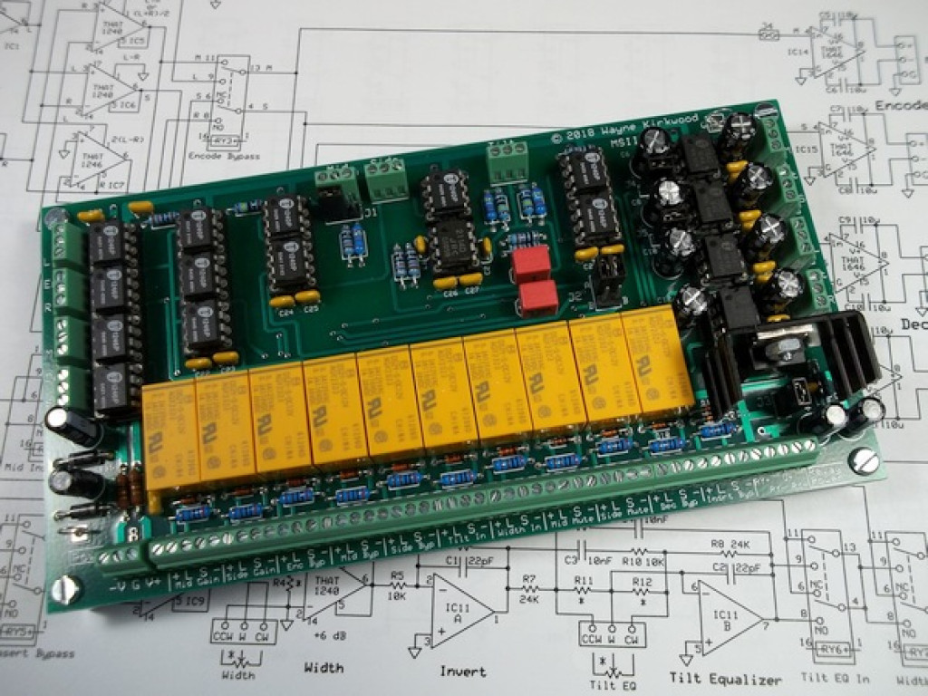
MS-II_600-1024x768.jpg

KA-Electronics.com MSII PC Board MS II Second Generation Matrix Mid-Side Encoder Decoder for Mastering Assembled and Tested PC Board
 
All good stuff, properly designed, specified, and proven on the bench.
 
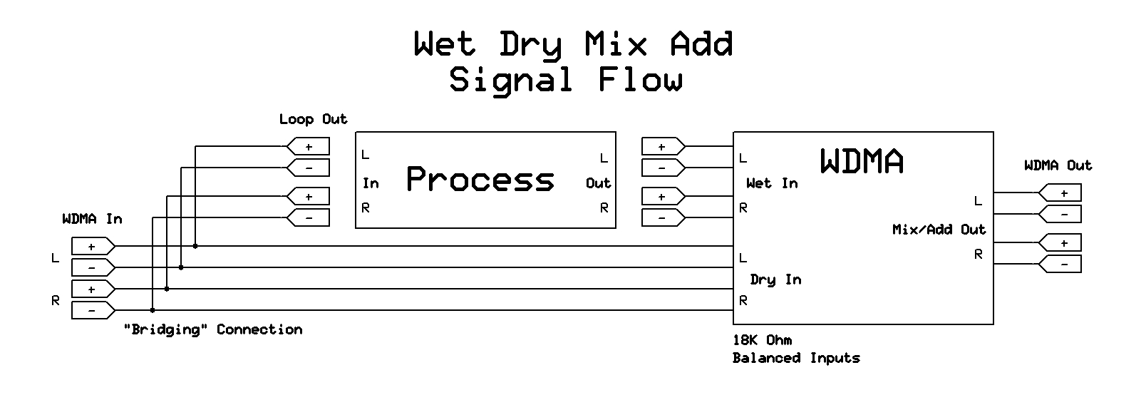
Wet Dry Mix Add Signal Flow

I get repeat questions about the signal flow for the WDMA and how it connects to the Process signal path.

https://ka-electronics.com/shop/index.php?route=product/product&product_id=124

The WDMA's 24KΩ balanced input simply bridges the Processor's Input and feeds the processor using a loop-through output.
A typical 50Ω/leg balanced output, when bridged by the 24KΩ balanced input of the WDMA, loads the source by less than a tenth of a dB.

Wet_Dry_Mix_Add_WDMA_Signal_Flow.jpg

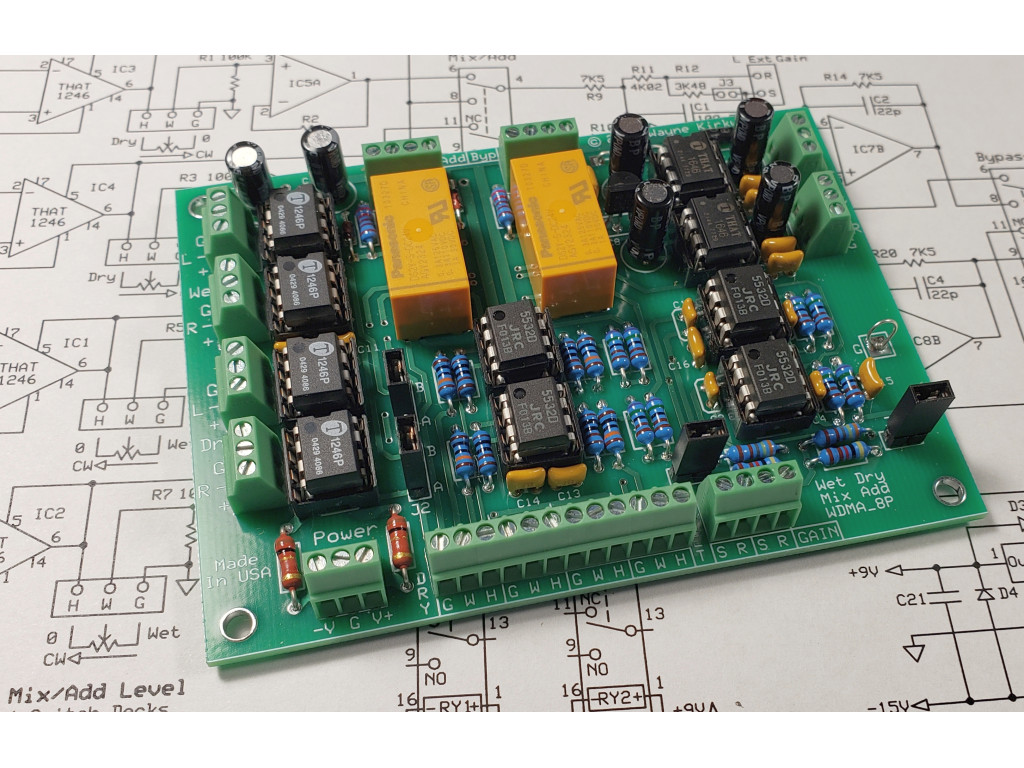
WDMA_Assembled-1024x768.jpg
Construction information and schematics: Wet Dry Mix Add Parallel Processor Construction Information - Pro Audio Design Forum
 
Last edited:
Hi Wayne I know it is not the right place. to put this ,but I've had this SC filter board for the se ll for nearly 12 years now and its about time I put it to use .
Is their any chance you still have the document for how to connect the frequency switch to the SC filter board and SC filter board to the main board..

Regards

DenisPhoto on 14-02-2023 at 01.17 #2.jpg
 
That board replaces C24 and C28.

For switchable HPF you'd need to flip four resistors R13, R17, R14, R18.

Back then I tried different freq, but finally settled on fixed 100k for -3dB @ 68Hz.
 
I found this document. Do you need the board schematic?
 

Attachments

  • Pico_Sidechain.JPG
    Pico_Sidechain.JPG
    37.8 KB
cheers Script and Wayne have you got the diagram ,for the switch connection to the Sc board , looks like it should be a four pole I am I correct in saying that .

regards

Denis

 
ok, so on the Sc board if I selected say 145hz would r13 and r17 be the same value 47k I believe ?

I will try to draw a diagram to show what I am thinking

regards

Denis
 
On a Pico stereo unit, all four resistors should be the same value. Cos would want the same HPF on both L and R.

For two mono boards, R13 & R17 form a pair in one channel, R14 & R18 in the other.
 
I have 2 of those boards but don't have the sch. Not sure I ever got them from Roger.
 
ok this is my thinking about switching the frequency ,only right side shown..


regards

Denis
 

Attachments

  • Photo on 14-02-2023 at 17.56.jpeg
    Photo on 14-02-2023 at 17.56.jpeg
    161.7 KB
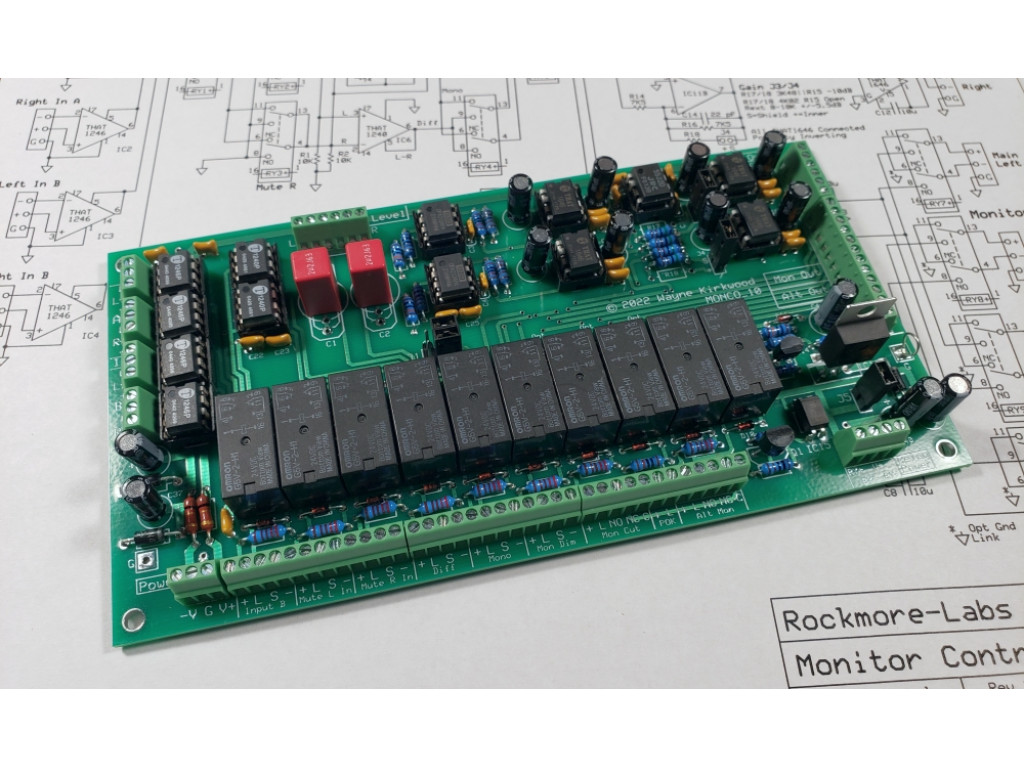
The KA-Electronics Monitor Controller, "Monco," is now available.
https://ka-electronics.com/shop/index.php?route=product/search&search=Monitor Controller
Monitor_Controller_Assembled_1000-1024x768.jpg

KA-Electronics.com Monitor Controller

Monco has the following features:
  • Two fully-balanced relay-selectable A/B inputs.
  • Two fully-balanced Monitor outputs, Main and Alternate, with mute relays and power-on/power-OK delay.
  • Fully-balanced Auxiliary output for A/D or Meter drive. Two jumper or switch-selectable gains (typ. 0 or -10 dB) or ±5.5 dB gain trim using an external 10KΩ control. (If using a stepped switch, shorting, make-before-break, contacts are required. Most Elma 15° 24 position switches are shorting.)
  • Monitor Attenuator Connector for external 2KΩ-10KΩ stepped switch or potentiometer.
  • Jumper or switch selectable source for the Aux Output. (Input A for driving an A/D input or follow monitor pre-attenuator for metering.)
  • Stereo, Mono and Difference monitoring. Can be toggled between any two modes by a single button press.
  • Monitor Dim. (-20 dB standard.)
  • Separate isolated +24V relay supply. On-board 7824 regulator or external +24V supply.
  • ±15V Power OK LED output.
Relay controls with LED outputs
  • Input B
  • Mute L; Mute R
  • Mono (L+R)/2; Difference (L-R)
  • Monitor Dim
  • Monitor Cut
  • Alternate Monitor
  • Each relay control has an on-board 2K21Ω current limiting resistor for approximately a 10 mA LED current. Power OK LED resistor is 10KΩ.
Mechanical and Power Specifications
  • Board Size: 6.3" x 3.3" Mounting holes: M3 on a 6" x 3" pattern. Assembled height: Approximately 1" not including stand-offs.
  • Power Requirements: ±15 to ±18V (max) approximately 65 mA (no signal current). +24V at 20 mA per relay/LED 200 mA maximum. Up to +36V using on-board regulator.
Audio Specifications
  • Inputs: THAT1246. Input Impedance 24KΩ differential, 18KΩ common mode. Maximum input level +27 dBu.
  • Outputs: THAT1646. Output impedance 50Ω nominal. Maximum output level +27 dBu.
  • Monitor Level Control: Input Impedance at the Wiper Connection 100KΩ. Recommended control value is 2KΩ to 10KΩ. Wiper AC-coupled -3 dB 0.7 Hz.
Monitor Outputs
  • Gain: +6 dB max; Dim -20 dB. Noise: -95 dBu at 0 dB gain, 10KΩ control at -6 dB attenuation. -96 dBu at maximum gain or full attenuation. Dynamic Range 122 dB.
  • Distortion: Output level +20 dBu into 10KΩ load. 1 kHz THD 0.00012%, primarily HD3.
  • Note: Monitor Outputs are relay-protected and will not operate until the differential supply voltage has stabilized to >27V (±13.5V) to provide turn-on/turn-off delay.
Auxiliary Output
  • Gain: 0 dB nominal. Noise: -98 dBu, -100 dBu A-weighted. Dynamic range 125 dB.
  • Distortion: Output level +20 dBu into 10KΩ load. 1 kHz THD 0.0001%, primarily HD3.
Note: Noise measurements are for a 20-20 kHz bandwidth and are unweighted unless specified. Maximum level specifications are for ±15V supplies.

Additional audio specifications and performance as they become available: Please refer to the forum.

To learn more about "Monco," the KA-Electronics Monitor Controller, visit the Pro Audio Design Forum construction thread.

The KA-Electronics Monitor Controller is sold as either a bare PC board, a "kit" (including 2 THAT1240, 4 THAT1246, 4 THAT1646 ICs, 2 OPA2134 and an NE5532), and the assembled and fully-tested module shown here.

A Mouser Electronics Project Manager bill-of-materials is available for DIY builds.​
 
Last edited:
Pico Compressor Stereo Edition PC Board and THAT4301 ICs available.

I just found a source for a small quantity of NOS THAT4301P that were purchased by a client when the parts went last time buy and have bundled them with the very few remaining Pico Compressor boards I held on to.

There is one Pico SE PCB with ICs currently available here: Pico SE THAT4301-based Stereo Compressor, Bare PC Board and ICs

I'll supply a zip file of documentation at the time of shipment.
 
Back
Top