Hi guys, sorry for delay with reply.
Had a little vacations, rest and back here.
Umit: the LED calibration procedure will be added ASAP, just let me get to workshop and free hour
")
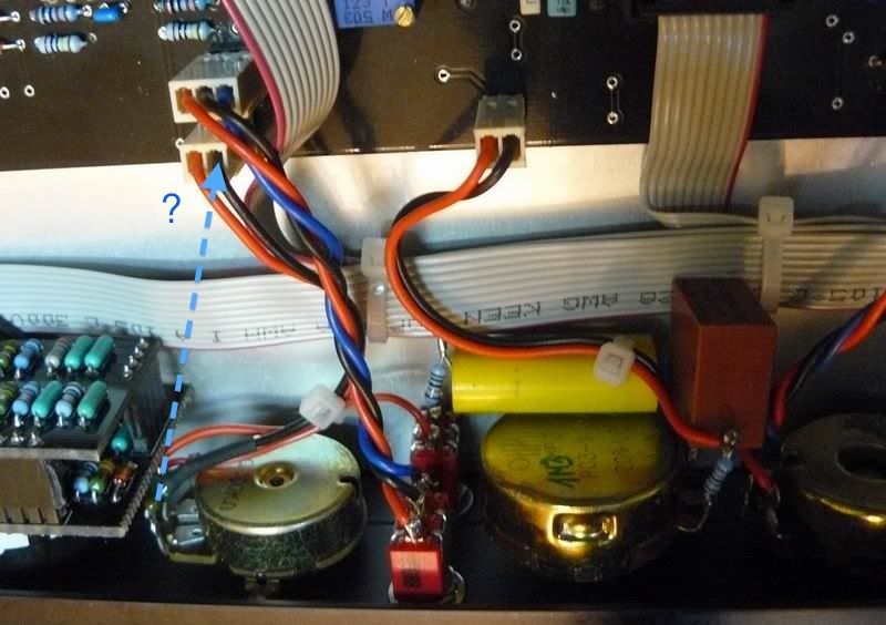
I assume, you assembling the full version, like mine.
This is not a standard option for attack/release, supplied with kits
(the kits are supplied with switch option, like an original compressor).
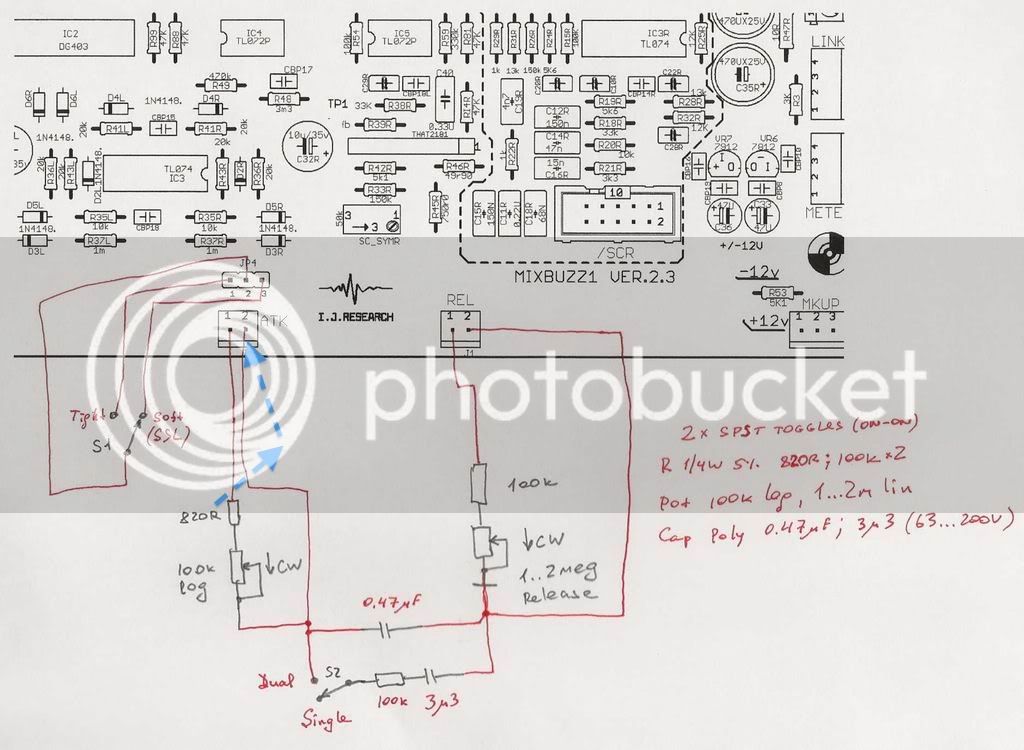
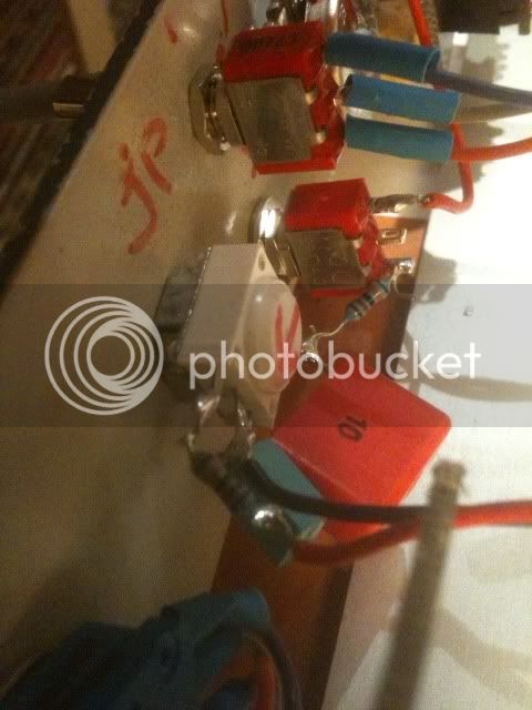
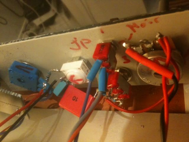
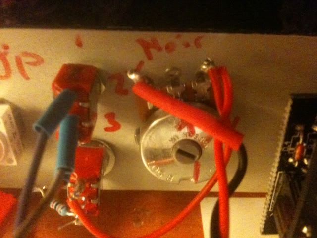
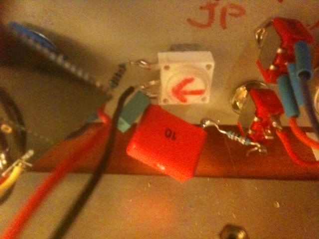
Instead of attack/release boards, it goes like here:
http://www.groupdiy.com/index.php?topic=40766.msg510118#msg510118
Please check as well attached photo....more-very soon....


![Soldering Iron Kit, 120W LED Digital Advanced Solder Iron Soldering Gun kit, 110V Welding Tools, Smart Temperature Control [356℉-932℉], Extra 5pcs Tips, Auto Sleep, Temp Calibration, Orange](https://m.media-amazon.com/images/I/51sFKu9SdeL._SL500_.jpg)