MixBuzz1 Build/Support thread

GroupDIY Audio Forum

Help Support GroupDIY Audio Forum:

This site may earn a commission from merchant affiliate links, including eBay, Amazon, and others.
If there are any mistakes, please report them to me.

I looked at the 4x2181 version and it look ok to me. 4x2181 in paralell arrangement. EDIT: checked the single vca too and it look ok.


Igor, the schematics differs in many ways from the THAT2002T-1-module. What version is your module actually based on?


I won't speak in name of Igor but to me this is not based on a 202 or 2002 vca. It look like the '202dbx to 2150 emulation' Jakob gave with the GSSL (lowest rightest part of GSSL schematic) but with 2181 ( hence some changes with trim parts values) and with 4 individual vca in // for Better noise spec than a single one.

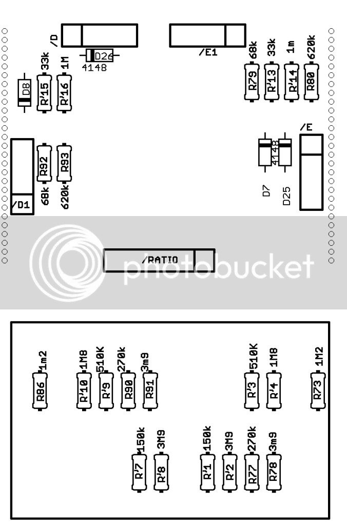
If you take a look at the 2181 datasheet it make sense: 20k R at input of individual vca, 5,1k R on VEE, 150k R on trim (between the value of 2181C and B version given in datasheet). 0R (jumper) for R6L/R and ferrite beads (or jumper) for R4L/R. It look really like the 'figure2: typical application' of 2181 datasheet. Add the OP275 (or 604) and adapt the feedback resistor R3 for 4 vca (20000/4= 5K =4k99) or just one with R3=20K... Here we are.

The 5534 is added as buffer for cv input iirc. I think it is here for mimic the 202xt behavior with cv too but it's beyond my understanding.
 
Today I got as far as getting the PSU running, everything seems to be working fine except for the -12Volt terminal.
At this stage the PSU is not connected to the Mainboard, should I even be seeing -12Volt yet? (looks to me like those regulators are on the mainboard?).

The relay's/logic common is marked -12V. Yes, I know, bit messy.
I used 12V switching mode power supply for first digitally controlled proto
(still in development, sitting on the shelf) and "-12V" marking for logic ground delivered from here.
-12V power supply point connected to ground, thus has zero potential ref. GND.
IIRC this was discussed some pages ago.

Second question, I seem to be missing C29L/R which is a 33pF in the feedback path of the TL072 straight after the control VCA.
Can I replace this with 22pF or 47pF? I don't have the exact same value handy.

20...47pf is fine here.
Last Question, what is the deal with the components labelled 'fb'? What value for R39L/R and R4L/R (these are both in series straight after the VCA)?

(figured this one out - all ferrite bead 0Ohm)

Ferrite beads. Helpful in case of fast op-amps like OPA2604 etc. Otherwise, use 0R jumpers.
Very last question, how are the VCA replacement boards connected to the main board? just sitting on wires?

Yes, use resistors or diodes cutted pins leftovers.

Mix  is working but I can't control it with the pot! I move it but nothing change!

Please check connection of MIX pot. Check for jumpers. If there is a problem,
probably, wrong connection or component value.

while the build up of the individual sections is very well documented, I am still unclear about how to connect all the PCBs:

On the side of the PCB are the following 4-pin molex connectors:

Bypass (switch and LED) - this goes to the EAO (bypass) switch - correct?
Yes!
CNB - this is for the leftmost toggle above the meter named 'Mix'?
Yes!
Link - just guessing here....'Turbo'?
Yes!

All these connectors are provided for illuminated pushbuttons or toggle+LED's...

Meter (+/- MTR, +/- LED) - signal and illumination for analog meter, not needed for LED meter??
Yes!

In the C&B parts bag was another 4pin molex M/F what is this for?

Connection of MIX switch.

Since writing the above I mananged to get the MixBuzz up and running.  
Grin Have jumpered off C&B and S/C Filter for the time being, as I am missing the dual 10k lin pot.
The biggest problem, however are the 10 pin dual row connectors.
I find it hard to see on the photos how the two terminals are meant to be connected for
Sidechain and LED meter connection. This really could do with clearing up in the documentation!
Also the dual row connectors that go on the ribbon cable keep breaking -
any tricks as to how to close these over the ribbon? Do I need a special tool?

Wise, as was answered post ago. Gently.

Pin1 usually marked on IDC females with small triangle or arrow, red wire of ribbons supplied with kits goes here.
IDC connectors are facing to same side.


Attachments

  • idc_wise.JPG
    idc_wise.JPG
    19.9 KB · Views: 27
About DBX202X replacement board.
After some thinking, I used simplest possible connection for 4x THAT2181, right from datasheet,
added same as on DBX202X control port...that's it. After comparing 202X and replacement board in MixBuzz500,
replacement board sounded RIGHT for me...as well as measured better.

DBX202X board has 8x 10K resistors inside; this way, we have to add input resistor (3k74) to "original" DBX202X.
My replacement board has 4x20k resistors, no need for "input" resistor-use jumper.
Same as was posted 3 posts ago by chriss:
http://www.elektroton.de/MixBuzz1/VCA_full.TIF

BTW.
Here is the picture of IDC 10 pin ribbon:
 

Attachments

  • idc.JPG
    idc.JPG
    40.3 KB · Views: 45
Igor said:
About DBX202X replacement board.
After some thinking, I used simplest possible connection for 4x THAT2181, right from datasheet,
added same as on DBX202X control port...that's it.
DBX202X board has 8x 10K resistors inside; this way, we have to add input resistor (3k74) to "original" DBX202X.
My replacement board has 4x20k resistors, no need for "input" resistor-use jumper.
Same as was posted 3 posts ago by chriss:
http://www.elektroton.de/MixBuzz1/VCA_full.TIF


Here is the picture of IDC 10 pin connector:

this applies to all 3 of them right? thanks.
 
Yes, of course. The lenghts will be different for 3 cables.
They depend on how pcb's placed inside the box.
In case of whatever: first, measure, think twice, than cut :)
 
Mix  is working but I can't control it with the pot! I move it but nothing change!

Please check connection of MIX pot. Check for jumpers. If there is a problem,
probably, wrong connection or component value.

Thanks Igor,
I found it ! 909Rs were not right ! I need to buy them.
The ratios pcb resistors are not clean also! I'll use 1,5 to 10
is it right for me ?
RATIO_152410_PCB.png

Thanks,
 

Attachments

  • RATIO_152410_PCB.png
    RATIO_152410_PCB.png
    35.7 KB · Views: 7
jandoste said:
Mix  is working but I can't control it with the pot! I move it but nothing change!

Please check connection of MIX pot. Check for jumpers. If there is a problem,
probably, wrong connection or component value.

Thanks Igor,
I found it ! 909Rs were not right ! I need to buy them.
The ratios pcb resistors are not clean also! I'll use 1,5 to 10
is it right for me ?
RATIO_152410_PCB.png

Thanks,

No!!!! This is for 1.5-2-4-10. RATIO_152410_PCB.png

For full ratios set = 1.5  2  4  6  8  10:
\Control_sidechain folder;
Front_btm.png is the file for full options RATIO.

909R: they are not in MIX control but in VCA control path......Strange :)
MMMMM...... In general: check every components are installed right way.....no shorts....no bad contacts....
Should work!

 
Igor said:
jandoste said:
Mix  is working but I can't control it with the pot! I move it but nothing change!

Please check connection of MIX pot. Check for jumpers. If there is a problem,
probably, wrong connection or component value.

Thanks Igor,
I found it ! 909Rs were not right ! I need to buy them.
The ratios pcb resistors are not clean also! I'll use 1,5 to 10
is it right for me ?

Thanks,

No!!!! This is for 1.5-2-4-10. RATIO_152410_PCB.png

For full ratios set = 1.5  2  4  6  8  10:
\Control_sidechain folder;
Front_btm.png is the file for full options RATIO.

909R: they are not in MIX control but in VCA control path......Strange :)
MMMMM...... In general: check every components are installed right way.....no shorts....no bad contacts....
Should work!

Now it works :) I put 820R [909R I didn't have]
Firebuzz! :) Nice sound !
 
I cracked a blue ceramic Cap with 104 on it.

What is a suitable replacement from mouser? Thanks. I just am VERY careful with this build as it is only my 2nd one (not careful enough though.... I soldered the cap in to high and pushed it down heating solder and a side cracked).

 
Hello igor,
This cnb funtion, can this be added to a gssl/sb4000?
I mean do you sell a CnB board that can be implimented into other projects?
 
piano said:
I cracked a blue ceramic Cap with 104 on it.

What is a suitable replacement from mouser? Thanks. I just am VERY careful with this build as it is only my 2nd one (not careful enough though.... I soldered the cap in to high and pushed it down heating solder and a side cracked).

Hi Piano, these are just power bypass caps and you can use a range of values to replace the one that is broken. To quote from Igor's BOM: "CERAMIC 2.5MM PITCH 47N...0.22UF" (that's anything from 47nF to 220nF or "473" to "224" in cap markings). If I remember correctly when I finished the build I had some of those spare, so with a bit of luck Igor might have put an extra one in your kit as well.
 
Now it works Smiley I put 820R [909R I didn't have]
Firebuzz! Smiley Nice sound !

MMMM lemmie doubt :)

Did you passed test procedure with 820R? All measures OK?
Hello igor,
This cnb funtion, can this be added to a gssl/sb4000?
I mean do you sell a CnB board that can be implimented into other projects?

Check forum for C&B boards, they are floating here.....
MixBuzz1 has C&B inside, and, in future, there will be a C&B board for 500 format predessor-MixBuzz500.
My personal opinion: GSSL has some really weird points, electronically and sound wise,
if somebody goin' to make a G4000 (6000) series on-board master compressor's clone,
better to keep the "original" way with some improvements depending on taste,
but not cloning the clone inherently done....as-is.

MixBuzz1 has better sound path than GSSL etc.
MixBuzz1 brought back to "original" and improved a bit with good line drivers/receivers.
Why not MixBuzz1?
:)
 
Hi Igor,
i am currently building my mixbuzz,
and i just noticed that you specify a 18vac transformer
i stupidly thought that this PSU needed a 15vac tranny like the previous GSSL boards,
and i allready have some 15vac transformer,
am i forced to buy a 18vac ?
Regards,
francois
 
Thank you so much for your help. This is a VERY complicated build for me - 3rd build - DRIP Pultecs were a walk in the park compared to this. I triple check everything.

Thanks for helping me out - means a lot!

[/quote]

Hi Piano, these are just power bypass caps and you can use a range of values to replace the one that is broken. To quote from Igor's BOM: "CERAMIC 2.5MM PITCH 47N...0.22UF" (that's anything from 47nF to 220nF or "473" to "224" in cap markings). If I remember correctly when I finished the build I had some of those spare, so with a bit of luck Igor might have put an extra one in your kit as well.
[/quote]
 
Sound's good but what do you think if I use 1k instead of 909r?
cheers

You can take some 910R - standard value, 5%- measure with ohmmeter-and choose pair of say 905 or 911R,
but exactly same value, within 1%.
909R were supplied with...strange.

Passing test procedure is necessary before talking about sound, it is kinda good tone :)

i am currently building my mixbuzz,
and i just noticed that you specify a 18vac transformer
i stupidly thought that this PSU needed a 15vac tranny like the previous GSSL boards,
and i allready have some 15vac transformer,
am i forced to buy a 18vac ?

Let's take a chance your 2x15V transformer gives a bit more volts...like most of'em do :)
Connect it to AC(edit: mains :) and measure the voltage on secondary.
If there's 2x17V but not less, and trafo rated as 25VA at least...ok,
let's call it "barely possible".......
Connect transformer to power supply; check the voltages from power supply without connecting to motherboard.
If all voltages are OK, please mind -12V at pover supply is actually logic(relay) ground,
measure voltage on power supply capacitors after diode rectifier (CP3, CP4), if they are in range 23...33V,
continue with the test procedure; if the voltages on (CP3, CP4) more than 23V when everything connected and ON,
it is possible to run MixBuzz1 power supply with 2x15V transformer.
Mind, when your mains goes some% lower than at the moment you measured the trafo voltages, there can be some hum.......

Thank you so much for your help. This is a VERY complicated build for me - 3rd build -
DRIP Pultecs were a walk in the park compared to this. I triple check everything.

Good point. To all people who building this compressor: yes, complicated, but cool and worth it.

Check every resistor with ohmmeter when installing. Check twice all components.
Take 30 min to meditate on schematics folder and 10 min to first post of this thread.
Than, probably, you will have questions, pass schemo's and test procedure again;
than, take some time to read this thread. Yes, time consuming, but trust me, it will save more of your time later.

If everything installed correct on PCB's and passing test procedure, you have absolutely cool sounding compressor :)
 
Hi igor,
many many thanks for your very explicative answer :)
very good voltage test procedure, thanks for the lesson !
As my transformers are 15va, i think i will not try to beat the devil
running them at 18V, i'm pretty sure it will stress them a lot,
and while it would be very interesting to verify if they can or not,
i will save them for another build and buy some strong 2x18v 30va to be on the safe side,
this jewel deserve a nice PSU to run it smoothly and hum-free ;-)
thanks again,
best regards .
Francois 
 
Igor said:
Sound's good but what do you think if I use 1k instead of 909r?
cheers

You can take some 910R - standard value, 5%- measure with ohmmeter-and choose pair of say 905 or 911R,
but exactly same value, within 1%.
909R were supplied with...strange.

Passing test procedure is necessary before talking about sound, it is kinda good tone :)

Thanks Igor,
I didn't get lots of resistors and I bought them from farnell ! I had some resistors
-250m / 650m / 750m etc etc but %20 of resistors were not right ! for me !
Cheers,

 
@pacemaker: 2x15V, 15VA will not work here.
I edited the typo BTW, connecting transformer to DC is..hehe...wrong :)
Thanx for pointing (or not :)


@jandoste: There is no
250m / 650m / 750m
resistor's values in MixBuzz1 at all!
The worst case is 3.9 meg used in ratios switch. Hmmmm...
but %20 of resistors were not right ! for me !
Kill me, for me too :)
Let's go one by one and fix it. Please check all resistors have right values.
 
Hi all,
I'm currently obtaining the components for this build. I need some help on the hex spacers.
Do you use M3 or M4 spacers. What material do you use, I know it must be metal in order to obtain contact between case and the ground centre hole on PCB. Any reason to use copper instead of aluminium for the spacers, or is this non-important?
Thanks,
 

Latest posts

Back
Top