Transistor amp from scratch

GroupDIY Audio Forum

Help Support GroupDIY Audio Forum:

This site may earn a commission from merchant affiliate links, including eBay, Amazon, and others.
I'm usually silent (because I don't know enough to say something relevant) but the way some of you do things here is really amazing and inspiring for people like me. There is such a talented group of people here. Thanks for sharing, DaveP and Ian among others, really.
 
good enough for prototype. ive never had any success with making pcb's but i have made the odd cylnder head from time to time. im much better with a lathe, milling m/c and die grinder. im so often in awe of the work on this forum
 
Yes. Copper side upwards. I might still have one of the early boards around somewhere. If I can find it I will take a pic and post it.

Edit: Found a pic (attached but a little blurry I am afraid) from December 2007.

Cheers

Ian

Nice. But I have to ask - didn't it take quite a time to remove the copper with a drill ? And we're you confident that the assembly would be sufficiently robust with the large components and did you mastic them ?
 
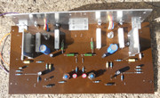
I have finished the board now with all the components in place:-


This is the under side:-


When I powered it up, I found out that the BC107 on one channel was a dud, I think I over-cooked it with the shrink fit tubing!
I was more careful with its replacement and I was then able to set the quiescent current for the output transistors to 15mA.

The fins on the heatsink were getting in the way of fitting it all in the box, so they have been removed.

Next job is to pass some audio and check the output signal and power output.

best
DaveP
 
Nice. But I have to ask - didn't it take quite a time to remove the copper with a drill ? And we're you confident that the assembly would be sufficiently robust with the large components and did you mastic them ?
To be 100% honest I cannot rememeber the exact process I used to remove the copper but from the pic you can see it looks fairly neat (which for something mechanical is unusual for me). If I was to do it today I would probably use a Dremel but 15 years ago when I made that board I definitely did not have one. I did have a pillar drill though so maybe that is how I did it.

As far as I rememeber there were no issues with robustness. I did not mastic them. Bear in mind this was meant for prototyping. Once I had the circuit working I taught myself to layout PCBs.

Cheers

Ian
 
I have finished the board now with all the components in place:-


This is the under side:-


When I powered it up, I found out that the BC107 on one channel was a dud, I think I over-cooked it with the shrink fit tubing!
I was more careful with its replacement and I was then able to set the quiescent current for the output transistors to 15mA.
Looks good.

IIRC typical quiescent current for bipolar class AB power amps is something around 26 mA. It should be stable thermally with .22 ohm emitter degeneration resistors and suitable heat sinking. Of course confirm that it does not thermally run away when hot.

The tell for inadequate class A quiescent current is crossover distortion at low level HF so input 20kHz audio sine wave at only a couple hundred mV and see how it behaves passing through class B transition (AC zero crossing).

JR
The fins on the heatsink were getting in the way of fitting it all in the box, so they have been removed.

Next job is to pass some audio and check the output signal and power output.

best
DaveP
 
The tell for inadequate class A quiescent current is crossover distortion at low level HF so input 20kHz audio sine wave at only a couple hundred mV and see how it behaves passing through class B transition (AC zero crossing).
Thanks for the tip John, I will try that. I will try to capture the sine wave but I'm not too good with cameras.

best
DaveP
 
OK, I have powered up both channels and found it necessary to change one component.

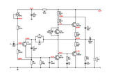
In the schematic below I have changed R2 from 120K to 100k because the Adjustment pot R1 ran out of adjustment.
I have also added all the voltages to check the current flows.


Using an 8 ohm load resistor, I got 9W before clipping on each channel. After this test the heat sink went to 26 degrees. Mullard did not specify the load resistance in their book.

best
DaveP
 
I believe the idle voltage before the output cap should be closer to 18V, actually 1/2 B+.
I think that reducing R2 would allow that.
How have you adjusted R1? For a given idle voltage of for best symmetry?
 
I believe the idle voltage before the output cap should be closer to 18V, actually 1/2 B+.
I think that reducing R2 would allow that.
How have you adjusted R1? For a given idle voltage of for best symmetry?

Yes, first of all I adjusted it for exactly half B+ but then when I wound it up it did not have symmetrical clipping so I readjusted it.
best
DaveP
 
To be 100% honest I cannot rememeber the exact process I used to remove the copper but from the pic you can see it looks fairly neat (which for something mechanical is unusual for me). If I was to do it today I would probably use a Dremel but 15 years ago when I made that board I definitely did not have one. I did have a pillar drill though so maybe that is how I did it.

As far as I rememeber there were no issues with robustness. I did not mastic them. Bear in mind this was meant for prototyping. Once I had the circuit working I taught myself to layout PCBs.

Cheers

Ian
i cant do pcb layouts i just get confused. im better at poin to point and just wing it a i go along
 
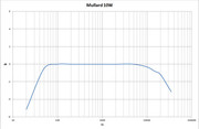
I tested the frequency response at the same 2W output as Mullard published. They reported within -3dB 20Hz to 35kHz.


The response at 35KHz is about the same but the low end is not. This is controlled by capacitor C3 and increasing its value by 100uF brings it back into spec.

Best
DaveP
 
The topology of this amplifier is fairly standard - something very similar is used in classic Calrec and Audix mixers from the 70s. However, some of the component values used in this particular design seem to me to be a little odd. First, the two collector resistors R9 and R10 drop 17V across them which implies a quiescent current of about 45mA which seems much too high to me for a driver stage unless the hfe of the output transistor is very low. Similarly the quiescent current in the input stage seems to be about 2mA and again its emitter and collector resistors seem rather on the low side. Perhaps there is some scope for improvement.

Edit: On the other hand for 8W into 8 ohms you need 1 amp rms current so maybe the driver does need 45mA bias current.

Cheers

Ian
 
In addition there's something weird with the LF response.
The input CR should have a turnover point of about 0.2Hz. With 100uf it should be 0.05Hz.
The actual response should be governed essentially by the output capacitor and the load impedance.
With 8 ohms, the turnover frequency should be about 10Hz.
 
Last edited:
The Mullard circuit description quotes total quiescent current 55mA and the output transistors 15mA.
Therefore there should be 40mA through the driver at B+ 30V, my B+ is 37V so its pushing more current through the driver.
The frequency response was tested at 2W as reported by Mullard so I did the same.

I used the following changes to capacitors:-
C3 400uF, I used 470uF.
C7 160uF, I used 220uF
C9 1250uF, I used 2200uF.
best
DaveP
 
A minor quibble about the trimpot R8 on TR3 the Vbe multiplier configuration. Good practice is to limit the adjustment range so you cannot inadvertently fry the outputs with accidental full class A bias.

Additionally trimpots have been known to fail open circuit (or open solder connections) so another good idea is to have the quiescent current trim go to zero class A current for open trimpot failure. This can be accomplished with the trim pot shunting across base-emitter.

This is obscure and arguably over engineering the design.

JR
 
C3 400uF, I used 470uF. with R4=22r => 0.1Hz
C7 160uF, I used 220uF with R9//R10 => 10Hz but actually irrelevant for low-level frequency response because under global NFB*
C9 1250uF, I used 2200uF. with 8 ohm load => 10Hz
* the designer has made a good job of making the bootstrap response matching the output cap response.
 
You could extend the bass response by making C3 1000mfd unless you just want to keep the specs you have. Putting some film bypass capacitors across all the 'lytics should help it sound cleaner.

I haven't read every post. What is the intended use for this amp? Is it a learning project, duplicating an old design? Just for Fun?
 

Latest posts

Back
Top