This is obscure and arguably over engineering the design.
JR
Maybe l. But I'd still say it's a good idea to take any failure mode into account esp when it's relatively easy to implement countermeasures.


This is obscure and arguably over engineering the design.
JR
IIRC I once looked at a older Mcintosh? (Not sure about this it was about 20 years ago, I think it was a Mcintosh because it had a glass panel) solid state amp.Yes, first of all I adjusted it for exactly half B+ but then when I wound it up it did not have symmetrical clipping so I readjusted it.
best
DaveP
The answesr to these questions are in the earlier posts.I haven't read every post. What is the intended use for this amp? Is it a learning project, duplicating an old design? Just for Fun?
I read them. I get it. I'm sorry you've been hit with that disease.The answesr to these questions are in the earlier posts.
best
DaveP
I don't recall seeing a PS in the schematic... think about all the high current path wires like low value resistors that will experience voltage drops from current flowing in them. Most of these voltage drops will be small and some can be ignored but take care that charging currents and speaker return currents don't corrupt signal reference nodes.Hi Dave
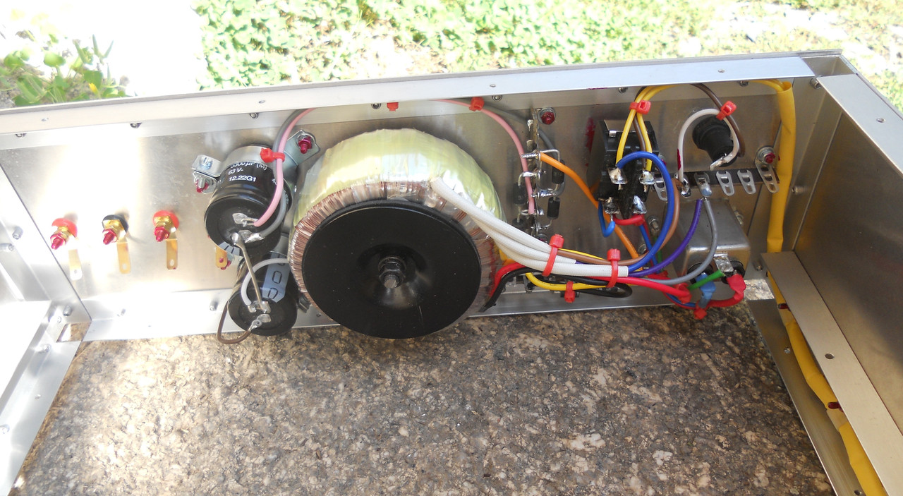
5. Your Power Supply will have excess HUM. The Rectifier + & - voltages need to go to big caps terminals, the output loads connect to the big cap terminals. The way you have them now the CHARGE & DISCHARGE currents share a common wire.
spoken like somebody who might have experienced that..... that is how we learn.6. The FUSE wiring should be wired with AC HOT going to the back side of the fuse so when removing the fuse, you can’t get shocked, if the AC HOT is wired to the ring, you can get shocked.
Duke
Didn't you mean TR2?2. Add Collector to Base cap so TR3 never can oscillate. Maybe 100pf?
Didn't you mean between collector and emitter?3. Add cap across TR3, Collector to Base. Maybe 10uF?
this is a thing many people forget about including myself. on occasion i have been taken by surprise with my own work,6 The FUSE wiring should be wired with AC HOT going to the back side of the fuse so when removing the fuse, you can’t get shocked, if the AC HOT is wired to the ring, you can get shocked.
Duke

this is a thing many people forget about including myself. on occasion i have been taken by surprise with my own work,
I have seen MANY original 1176's and possibly other UREI / UA products of that vintage with this issue. It's the first thing I look for when I open one up. End topic swerve...I have updated my post #88
6. The FUSE wiring should be wired with AC HOT going to the back side of the fuse so when removing the fuse, you can’t get shocked, if the AC HOT is wired to the ring, you can get shocked. This is a requirment to meet /qualify to get UL/CSA and others.
Duke
I normally use an IEC socket with a built in fuse. Meets UL and CE.I normally wire the fuse straight after the mains inlet before the switch. But, probably not so much of an issue if one doesn't live in the U.K
So do I, but on the rare ocassions I fit a seperate iec inlet and fuse holder the fuse is the first thing after the iec inlet.I normally use an IEC socket with a built in fuse. Meets UL and CE.
Cheers
Ian
Can you please elaborate? Do you mean a film cap across all lytics, even the AC coupling ones like C1? I don't recall ever seen a schematic with a film cap across an AC coupling capacitor. Why would this improve the sound and what value should be chosen? ThanksPutting some film bypass capacitors across all the 'lytics should help it sound cleaner.
This has been done, thank you for the tip6. The FUSE wiring should be wired with AC HOT going to the back side of the fuse so when removing the fuse, you can’t get shocked, if the AC HOT is wired to the ring, you can get shocked. This is a requirment to meet /qualify to get UL/CSA and others.
I don't understand what you mean, the +and- from the rectifiers go to the 3300uF caps and then to the amps.5. Your Power Supply will have excess HUM. The Rectifier + & - voltages need to go to big caps terminals, the output loads connect to the big cap terminals. The way you have them now the CHARGE & DISCHARGE currents share a common wire.