Upacesky
Well-known member
2 for me too


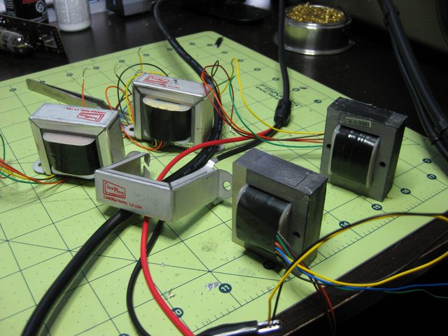
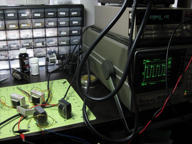
[tt]On other things, I am still trying to get a quote from David at Cinemag for the transformers :( I have shot him a couple of emails, but it does not seem that after our initial conversation he has had the time to answer it.

Does anybody know another way to contact him? I don't want to be bother too much, but it is kind of one of the critical pieces in the design...

kvothe said:And you could put me on the list for a pair, great idea and timing")
Indecline said:Count me in for a pair. I've been eyeballing the 444 for some time now.
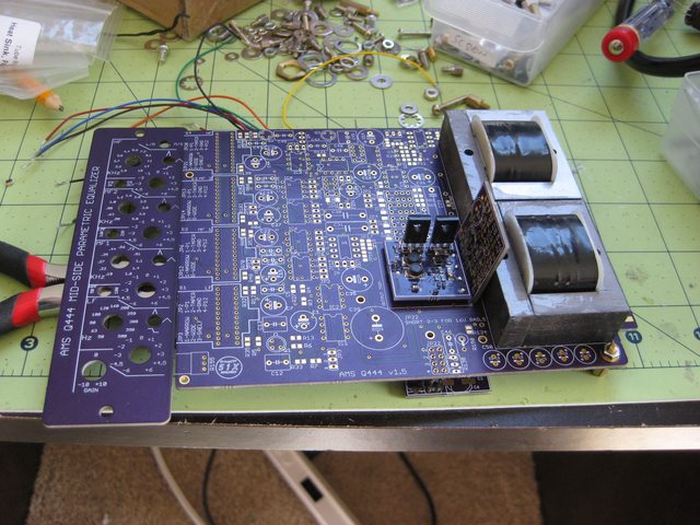
Super surprised you were able to cram it into 500 series format!
What are the gain steps in?
at least in the prototype. It will be +/- 7 or 15dB with a center detent at 0 dB.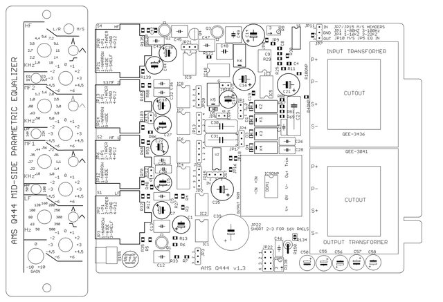

All "stock" 333c,s have a 4:1 bridging input transformer with the first gain stage modified to make up the level, and the final amp stage has a 1k rev-log level pot to give +/-15db of gain adjust. ("stock" since the 333c was custom built for only two consoles, Lions Gate films and The Cary Grant dub theatre at what is now Sony pictures). The input transformer is completely responsible for the sonics of this version of the eq and the 30 step precision pots on frequency select and gain/cut make it one of the most versatile and flexible eq,s of its type. Add the continuous swept HI/Low pass filter pots and you have an eq that is very hard to beat for twice its value (which is a lot more than you managed to get your 333c for).
Enter your email address to join: