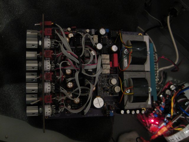
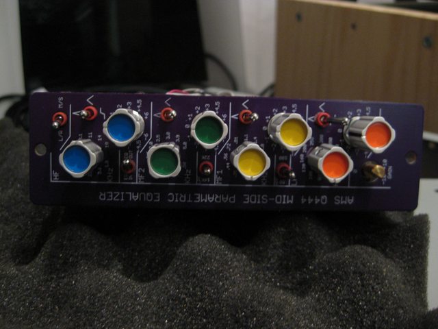
Feeler: Quad 8 444 EQ with M/S extension in 51x format.

GroupDIY Audio Forum

Help Support GroupDIY Audio Forum:

This site may earn a commission from merchant affiliate links, including eBay, Amazon, and others.
Hi,

I'm in for a pair of these. If you're happy to share your final FPE file I may have my own panels made so I can pick a gaudy anodised colour though...

Cheers.
 
rob_gould said:
Hi,

I'm in for a pair of these. If you're happy to share your final FPE file I may have my own panels made so I can pick a gaudy anodised colour though...

Cheers.

I am happy to share anything ;) But you would probably want to wait till I get the final design.

For example, on my current prototype with a PCB front panel I drew the frequency values way too close to the opening, and the result is that even with the thinnest  knob you partially cover those on the MF1 frequencies.

BTW, how is that only europeans are interested in this? :p
 
So far the changelist for revision 1.6:

1. Adding 1M load resistor after high pass as per schematic.
2. MAJOR: U2 (mid/side to L/R) is now placed *after* the gain switch instead of before. On the current circuit the gain pot has no effect of the mid/side balance as it was placed after the L/R mode was restored by the THAT1240 (d'oh, thanks I did a prototype... how could I miss that) fortunately there I could manage to workaround it with some cables and cutting some traces.
3. MAJOR: On current design pins A-V are wired, they should be disconnected for compatibility with any lunchbox.
4. MAJOR: Adding jumper between chassis ground and power ground.
5. Changing footprints for transformers from 4 wires to 6 wires.
6. Adding back zobel network footprints on secondaries of transformers. (In case anybody uses other transformers)
7. Adding footprint for Jensen input transformer alternative
8. Changing gain resistor to a trim to allow better calibration on stereo configs
9. MAJOR: Adding connection from transformer shield to chassis ground.
A. MINOR: Readjust mechanicals on PCB to bring the gain pot slightly forward
 
A small update, as I would probably need a bit of help with the DC to DC converter...

It is ALL wrong :p Not a bit issue because it was the cheapest part of the circuit and I designed it in a couple of hours using free space in the test panel...

The issues are two fold:
For the negative voltage... well it burned like there was no tomorrow... Thick black smelly smoke and the MIC4690 in fumes. I dont know why it did that. I designed it based on http://electronicdesign.com/boards/turn-positive-buckboost-circuits-negative and I believe that first the circuit in figure 4 is wrong (GND should be tied to the output) and I probably asked too much from the part.

For the positive voltage nothing in the output... but I expect that is is asking too much current, as it shuts down the +16V powersupply for over-current condition...

So this is the circuit...

Anybody can help?
 

Attachments

  • booster.png
    booster.png
    6.8 KB
On the other hand. I tested the AM10 in 2520 format and I am very, very happy with it.

It is very close in sound to a 990C opamp, with a tad higher distortion (probably as it was under-biased with a +/- 16V power), it seems to have a more extended frequency range than the gar2520 both in both ends of the spectrum... without being harsh.

I am thinking of making it public now and allow people to get one of those... PCB + parts is under $15 :)
 
Upacesky said:
I can't help with the dc-dc, but Im feeling quite excited by this project. Keep up the good work, and thanks for updating this regularly

I think it is better  to do it that way :)

So far have been verified:
1. The opamp.
2. The complete gain chain without any EQ from transformer in to transformer out.
3. High-pass/Low-pass filters and relays.
4. EQ IN relay.
5. LF frequency controls and response
6. MFI frequency controls and response

Failed verification:
1. DC-DC coverter (quite spectacularly actually)

Debugging:
1. Frequency calibration


Well, I finished the first prototype... and I am quite happy. Taking into account everything that goes under is very silent and just running it flat gives a nice sound (maybe my opinion). The AM10 does give something in the high end, and the irons are nice... I would love to run it in full +/- 28V to try a bit its more colored saturation :)

It is running in its standard configuration with +/- 16V rails.

Any feedback? Do you like it? I am going to apply the changes i detected in the prototype and ask for people that want to participate in the initial run. Just a comment, this baby is really difficult to build and I seriously recommend that you chose some knobs that allow to grab the controls easily... it is packaged *REALLY* thigh.

https://soundcloud.com/david-martinez-nieto/sets/ams-q444-prototype

PFTA5uZl.jpg

F9x7rjMl.jpg
 
Nice Prototype! Well done. Following with interest.

BTW, did you solve the problem with the DC/DC Converter?
Couldn't find any obvious errors in the schematic you posted either.
Did you check all parts values and the direction of the diode?

Best,
Carsten
 
culteousness1 said:
BTW, did you solve the problem with the DC/DC Converter?
Couldn't find any obvious errors in the schematic you posted either.
Did you check all parts values and the direction of the diode?

Best,
Carsten

I didn't try, I was busy verifying the protoype... I'll take a look sometime this week.
 
My only gripe with the circuit is that, as is, in order to support the M/S matrix I am forced to implement a much higher resistive element that I wanted... on the voltage divider... Which in turn means higher noise.

The original Q444 had fixed gain of just 6.81dB, which managed to keep the noise levels at <1mV RMS... As is, the Q444 has 4.51mV RMS (The last stage has 25dB gain). I am going to have to diverge slightly from the original design to reduce the noise by introducing a voltage follower between both stages
 
I have finalized the testing of the prototype and I am happy to say that I managed to get the noise to -70dbu (20-24KHz) with a 600 Ohm load... this is less 0.25mVRms of input referred noise for the bandwidth from 10Hz-24KHz. This is 1.58uV/Hz^0.5 of input referred noise. Maximum noise is at -60dBu (with 10dB gain)

That means that while the noise will be still audible (-90dBFs for a 0dBFs=>20dBu interface, so barely 6dB above the 16 bit dynamic range) but should be low enough to be usable as the last element of a chain.

For me the golden standard is -76dBu, that is achievable by reducing headroom. Right now it is calibrated to a +28dBm max input, but it should be possible to reduce the noise level even more
 
dmnieto said:
I have finalized the testing of the prototype and I am happy to say that I managed to get the noise to -70dbu (20-24KHz) with a 600 Ohm load... this is less 0.25mVRms of input referred noise for the bandwidth from 10Hz-24KHz. This is 1.58uV/Hz^0.5 of input referred noise. Maximum noise is at -60dBu (with 10dB gain)

That means that while the noise will be still audible (-90dBFs for a 0dBFs=>20dBu interface, so barely 6dB above the 16 bit dynamic range) but should be low enough to be usable as the last element of a chain.

For me the golden standard is -76dBu, that is achievable by reducing headroom. Right now it is calibrated to a +28dBm max input, but it should be possible to reduce the noise level even more

I would sacrifice some headroom if it meant dropping the noise below an audible level.

How audible is it? (I'm not quite smart to interpret those noise figures just yet ;) )Maybe not for classical music but could it work for acoustic singer/songwriter type of stuff? Or maybe just rock n' roll? 8)

 
With the new changes I dropped the noise floor to -91dBV, which is very, very low. You will be able to measure the noise if you are recording at 24bit, but it falls way below the 16bit dithering level... even at 10dB gain. You would not be able to hear it.

There is the possibility, if you use an amplifier after the EQ, that the white noise would be audible. In that case, an option is to replace the TL072 for lower noise opamps (there are 4 of those)

I am receiving some low noise opamps next week (LME49710 and OPA2134) which should drop the noise level even more...

In summary, yeah, you should be able to use it, probably even with classical music
 
Well done on going from schematic to proto so quickly. 

As a mastering engineer the main reason I couldn't use this build is ergonomics.  For me the space between knobs and the 1dB steps would rule it out for me.  I realize that this is much more likely to be a bus EQ for a space challenged engineer/mixer rather than a purist mastering tool.

Again well done on dealing with the noise issue so quickly.  Absolute levels of noise are only part of the discussion, the character of the noise is equally important.  For example my Pendulum OCL2 is very noisey but mostly at very low frequencies which is very tolerable for my work.

 
Back
Top