PRR-176 Vari-Mu REV 2 - *Group Buy 7/13!*

GroupDIY Audio Forum

Help Support GroupDIY Audio Forum:

This site may earn a commission from merchant affiliate links, including eBay, Amazon, and others.
I'm gradually acquiring parts for the Vari-mu, for use with the AC Sound pcb set.

This will be my first construction involving tubes, and I note that a 6bc8 is specified for this project.

Can I get some ideas of preferred tube brands and alternative types, which are suitable for the project, as well as reputable places to buy from?

Basically I have little idea what to look out for, so any help is appreciated.

Cheers,  Paul H
 
prh said:
I'm gradually acquiring parts for the Vari-mu, for use with the AC Sound pcb set.

This will be my first construction involving tubes, and I note that a 6bc8 is specified for this project.

Can I get some ideas of preferred tube brands and alternative types, which are suitable for the project, as well as reputable places to buy from?

Basically I have little idea what to look out for, so any help is appreciated.

Cheers,  Paul H

Ive used different kinds and honestly haven't really been able to tell a difference...not that i was specifically looking for one, but seems like any decent 6bc8 tube works fine here. other peoples experience might be different though.
 
Heres some sound samples I put together, and thought I would share them. I'm using pretty much stock stuff....1uf Tant cap, ne5534 on input API type opamp 2520 on output. Cinemag input and PM1000 1:1 output for interstage:

https://docs.google.com/open?id=0BzDAglyU_ZBAbm5CV1pNVFo3SE0
 
Almost done with this project but had a couple issues that I wanted to ask about. I'm using GAR1731 DOAs for input and output gain, and INA/DRV chips on ins and outs. All PS voltages read correct. On the output pins of the output 1731s, there is between 250 and 400 mV of DC offset (does this seems excessively high?). It seems like this DC is being passed to the DRV chip then essentially being doubled on the xlr. Should the output of the 1731 be cap coupled? I do have some 600/600 edcors that I could throw on the output instead, preceded by the bi-polar cap, but I'd like to get the chips working. Would it really be necessary to have a bi-polar cap in this situation if I'm only reading a positive offset voltage on the output of the 1731s?

Where should the max of the needle be when I calibrate the Hairball's 8027-WF 1mA meters? Where should I take the voltage from to power the leds in the meters? Should I run them in series (seems to make the most sense)? I don't want to draw any more current from the heater circuit as it already seems to be running the regulator pretty hot, unless perhaps I could take it pre-regulator. Do I have to throw a high wattage resistor in series to drop down the voltage? Any idea what those leds can take?

Thanks for this project Abe! PS, when are you going to get a board for that PI compressor  ;).

Brian

 
kramerb1 said:
Almost done with this project but had a couple issues that I wanted to ask about. I'm using GAR1731 DOAs for input and output gain, and INA/DRV chips on ins and outs. All PS voltages read correct. On the output pins of the output 1731s, there is between 250 and 400 mV of DC offset (does this seems excessively high?). It seems like this DC is being passed to the DRV chip then essentially being doubled on the xlr. Should the output of the 1731 be cap coupled? I do have some 600/600 edcors that I could throw on the output instead, preceded by the bi-polar cap, but I'd like to get the chips working. Would it really be necessary to have a bi-polar cap in this situation if I'm only reading a positive offset voltage on the output of the 1731s?

Hi! Yea the DRVs do seem to pass DC. They supposedly are supposed to negate it by having the caps near the output but I guess not. (from the data sheet) I would put a cap between the opamp and the DRV chip. Bi-polars are ALWAYS a fine choice when dealing with audio, or anything for that matter.

Where should the max of the needle be when I calibrate the Hairball's 8027-WF 1mA meters?
The higher the needle the more resolution it will show. Doesn't matter, wherever you want it.

Where should I take the voltage from to power the leds in the meters? Should I run them in series (seems to make the most sense)? I don't want to draw any more current from the heater circuit as it already seems to be running the regulator pretty hot, unless perhaps I could take it pre-regulator. Do I have to throw a high wattage resistor in series to drop down the voltage? Any idea what those leds can take?
Run them off the negative rail, run them in series and try a 1k to 10k (i forget exactly what I used last build) depending on how bright you want them. And because you are running them off the negative rail, jsut remember to wire it up correctly (positive to ground, neg to neg power)

Thanks for this project Abe! PS, when are you going to get a board for that PI compressor  ;).
Your welcome, home you get some good use out of it! Also I'm getting ready to do a kickstarter for the Pi.... :)


Brian


[/quote]


Also I've been doing some more testing and it seems without shielded transformers on the input and interstage, the transformers are very susceptible to hum pickup.
 
Hey I finished the second channel of mine--love it! Last session it handily beat both my rev a 1176, rev d 1176, and la2a clones in a blind test for a particular vocalist's track.
The stereo matching is working very well too (nearly identical GR up to 10dBs).

The only issue left to resolve is the side-chain high-pass: It doesn't seem to have an audible or measurable effect on gain reduction.
Any clues for troubleshooting?
 
ethervalve said:
Hey I finished the second channel of mine--love it! Last session it handily beat both my rev a 1176, rev d 1176, and la2a clones in a blind test for a particular vocalist's track.
The stereo matching is working very well too (nearly identical GR up to 10dBs).

The only issue left to resolve is the side-chain high-pass: It doesn't seem to have an audible or measurable effect on gain reduction.
Any clues for troubleshooting?

Great news!! Yes for the HPF, you might want to put a smaller cap in there for a more audible HP. You could even do one super small so to give it a de-esser type control.
 
Both this and the clx 160vu are great projects. I especially like how many options can be played with on this board. Can't wait for that pi
 
abechap024 said:
Great news!! Yes for the HPF, you might want to put a smaller cap in there for a more audible HP. You could even do one super small so to give it a de-esser type control.
Thanks Abe. Unfortunately, changing the cap out for a smaller value didn't change anything. I added sockets for trying different values and even with a .01uf in place, the HPF switch won't affect the level of compression for a 20hz tone. Perhaps I'm missing something obvious?
 
ethervalve said:
abechap024 said:
Great news!! Yes for the HPF, you might want to put a smaller cap in there for a more audible HP. You could even do one super small so to give it a de-esser type control.
Thanks Abe. Unfortunately, changing the cap out for a smaller value didn't change anything. I added sockets for trying different values and even with a .01uf in place, the HPF switch won't affect the level of compression for a 20hz tone. Perhaps I'm missing something obvious?

Doh! You know what, I think those caps are labeled backwards. Try putting the HPF in the one labeled 1uf. Thanks for catching that...
 
abechap024 said:
Doh! You know what, I think those caps are labeled backwards. Try putting the HPF in the one labeled 1uf. Thanks for catching that...

Can you clarify this please?
 
abechap024 said:
ethervalve said:
abechap024 said:
Great news!! Yes for the HPF, you might want to put a smaller cap in there for a more audible HP. You could even do one super small so to give it a de-esser type control.
Thanks Abe. Unfortunately, changing the cap out for a smaller value didn't change anything. I added sockets for trying different values and even with a .01uf in place, the HPF switch won't affect the level of compression for a 20hz tone. Perhaps I'm missing something obvious?

Doh! You know what, I think those caps are labeled backwards. Try putting the HPF in the one labeled 1uf. Thanks for catching that...
Excellent! That's all it took. Works great.
 
prh said:
abechap024 said:
Doh! You know what, I think those caps are labeled backwards. Try putting the HPF in the one labeled 1uf. Thanks for catching that...

Can you clarify this please?
Hi prh, he just means the caps labelled C1 and C35 on the PCB should change places in channel one; C38 and C36 should switch places for channel two.
 
ethervalve said:
Hi prh, he just means the caps labelled C1 and C35 on the PCB should change places in channel one; C38 and C36 should switch places for channel two.

Ah, thanks for that!
 
DAN_000 said:
Hi,

Should I use R7-R8 and R87-R95 when in center tap mode ?  Im using 1540 on both input and interstage.

thanks
Would also like to know what the practical difference is between using center tap or resitors?....
 
Just did center-tap myself.
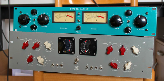
Here is a pic of my build:


The PRR is obviously the one on top, Fester's TG on bottom. Copy RCA knobs, hairball meters. LL1540  as inputs and interstage, gar1730 on first DOA, gar2520 on output. Chip balanced output. Used the german groupbuy toroid.

Two more quirks to iron out, one channel compresses, the other one kind of expands.. the meter moves forward a tad when compressing. Must be a wiring fault or cold joint somewhere.

The other is that VU meter bulbs need some juice, so I'll probably just take the 20-0-20 out from the transformer. One of the "20" windings has 1A current available, the other 0.5A, so I'm thinking to rectify the 1A separately, smooth out using a 2200uF and that should be it. The bulbs are rated 12V 100mA. I've measured resistance on one and it's 12Ohms, so putting 24Ohms for two in parallel PSU designer says they would be getting 9.9VMRS.

Also, here is the usual sound sample:

https://dl.dropbox.com/u/12679166/prr176/jazzvoc_off.wav

https://dl.dropbox.com/u/12679166/prr176/jazzvoc_prr176.wav

Cheerio.

astroschnautzer said:
DAN_000 said:
Hi,

Should I use R7-R8 and R87-R95 when in center tap mode ?  Im using 1540 on both input and interstage.

thanks
Would also like to know what the practical difference is between using center tap or resitors?....
 
Dr_J said:
Hey baadc0de,

this is a cool frontpanel and cool knobs as well!!  :D

Thanks mate.. unfortunately, I'm still struggling to get the 1st channel to compress. I've checked the wiring, components.. slowly getting out of ideas. Getting my scope up, we'll see what's happening in there.

EDIT: seconds after the post, I found C33 to be in the other way around. Changed it, no luck, changed ICs, still no luck. The scope sees -1VDC at output of D1/D2. So I guess it should be the wiring..

PS: there is correct movement on the 1st channel's GR meter when they are in link mode. I can't verify audio since I only have two cables at home :)
 
baadc0de said:
Dr_J said:
Hey baadc0de,

this is a cool frontpanel and cool knobs as well!!  :D

Thanks mate.. unfortunately, I'm still struggling to get the 1st channel to compress. I've checked the wiring, components.. slowly getting out of ideas. Getting my scope up, we'll see what's happening in there.

EDIT: seconds after the post, I found C33 to be in the other way around. Changed it, no luck, changed ICs, still no luck. The scope sees -1VDC at output of D1/D2. So I guess it should be the wiring..

PS: there is correct movement on the 1st channel's GR meter when they are in link mode. I can't verify audio since I only have two cables at home :)

Build looks great! I had trouble with one of my builds doing exactly what you were saying and it turned out to be a bad bypass switch. So I would double check around the bypass wiring, and solder joints...the channel that isn't compressings' tl072 and sidechain area.
Good luck!
 
Back
Top